
Heat:Chair
Can We Fabricate The Most Efficient & Personalized Chair Through Robotic Heating?
Work at Harvard GSD | 2018 Collaborator: Sulaiman Alothman Advisor: Prof. Sawako Kaijima Skills: Computational Design, Robotic Fabrication, Systematic Design
Brief
Heat:Chair is an integrated computational fabrication system that applies the first-hand material knowledge we gained from experiments
into the digital generation of form and the robotic distribution of material properties (stiffness) in the form.
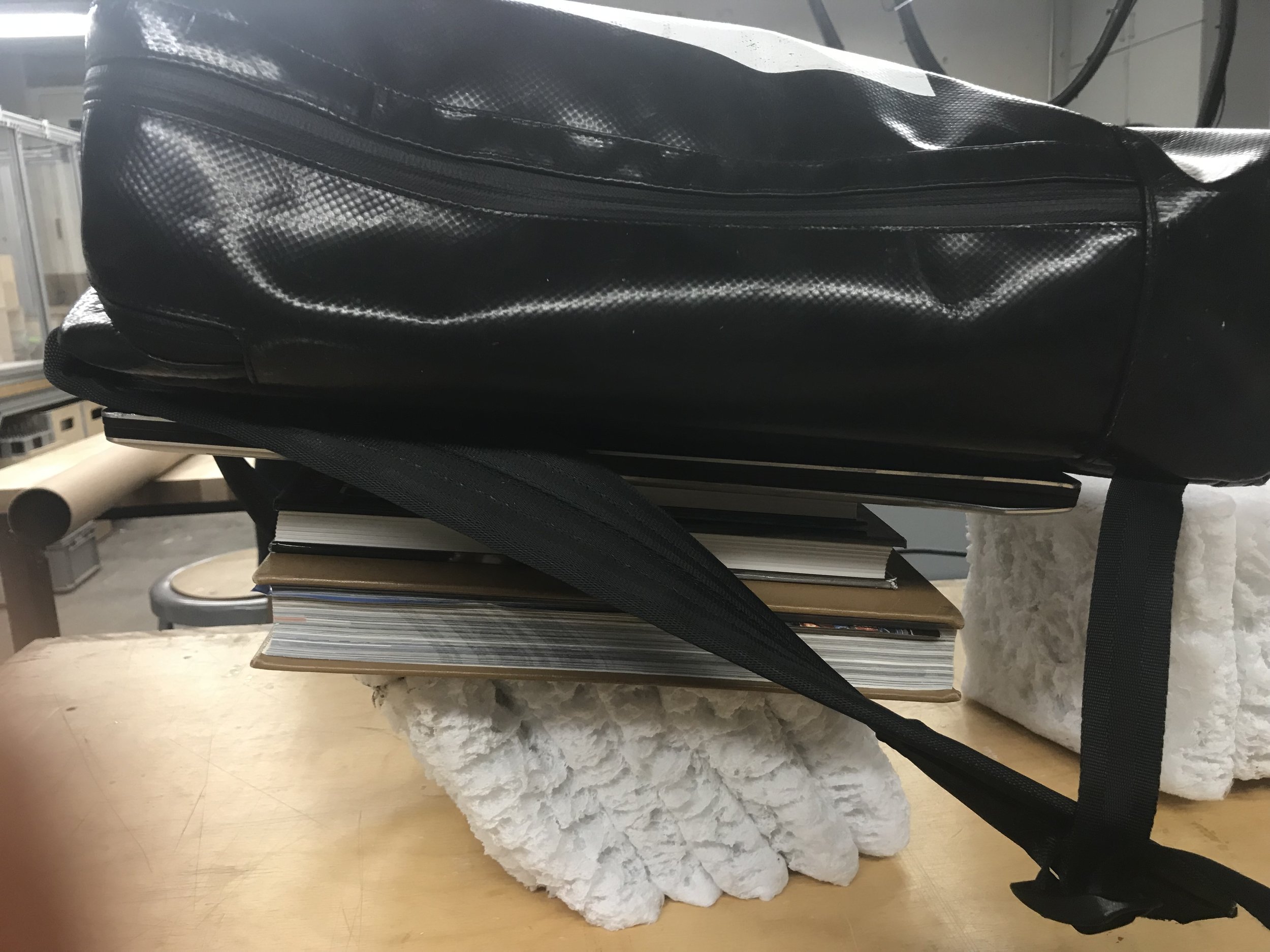
The heated chair is able to support 180 kg load from 6 different sitting directions with an ultra lightweight material, polyester.
Precise local stiffness control was achieved through programmed robotic heating and folding,
making it not only the most “efficient” chair, but also the most personalized chair.

Precedent

Our Goals
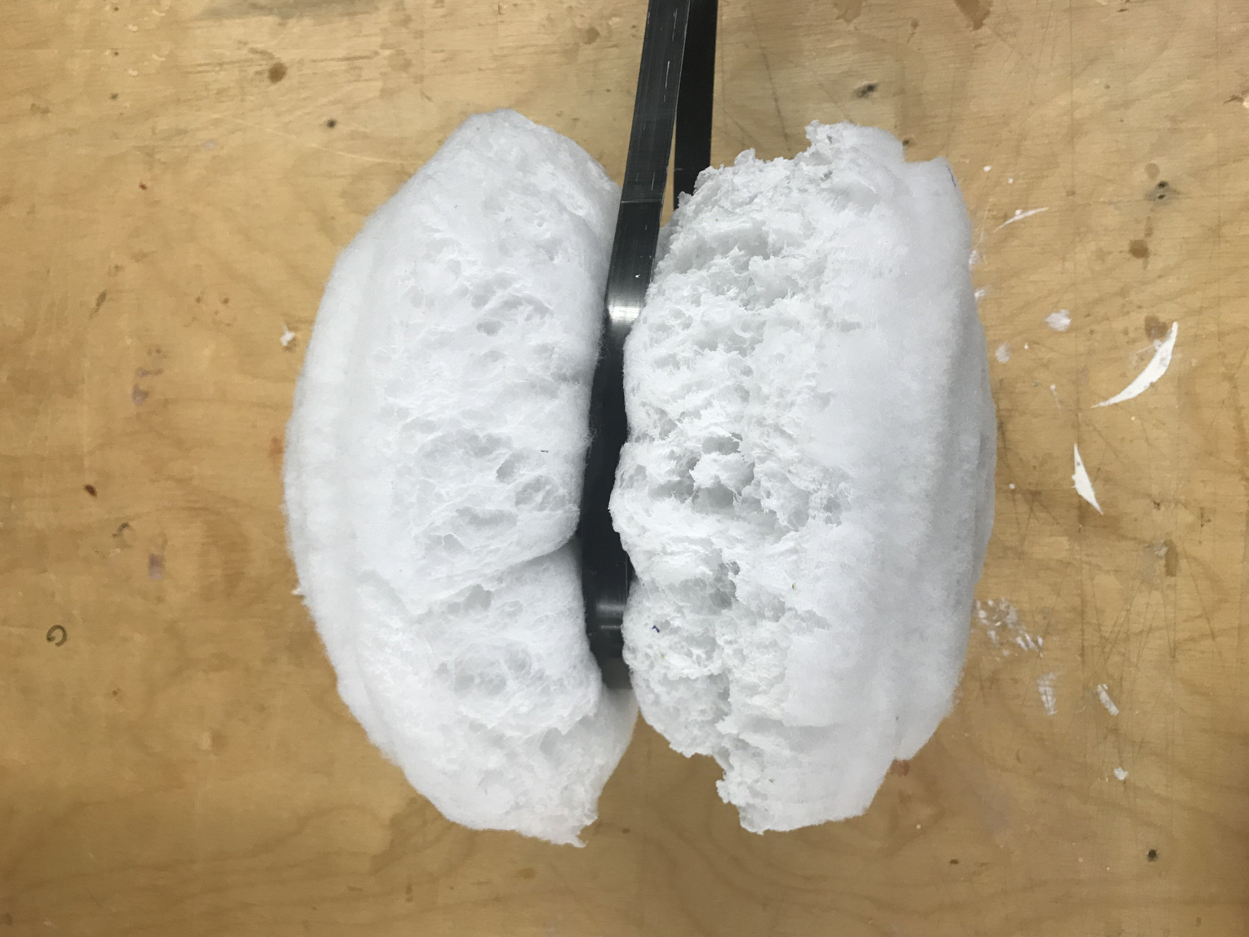
Pane Chair has a few limitations (or features): 1. The baked result is “unpredictable”, lacking the controllability for local stiffness.
2. The raw material - polyester chunk is hard to acquire & transport 3. The fabrication process can’t be automated.
To address these limitations, we aim to develop an integrated computation and fabrication process that is able to
1. achieve precise/smart control of local stiffness variation 2. use raw material that is more affordable - polyester fiber sheet
3. automate the fabrication process 4. express a wider range of aesthetics.

Our Approach
We diverged into 3 explorations: Material, Fabrication and Computation before converging onto the final solution.
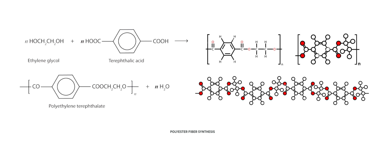
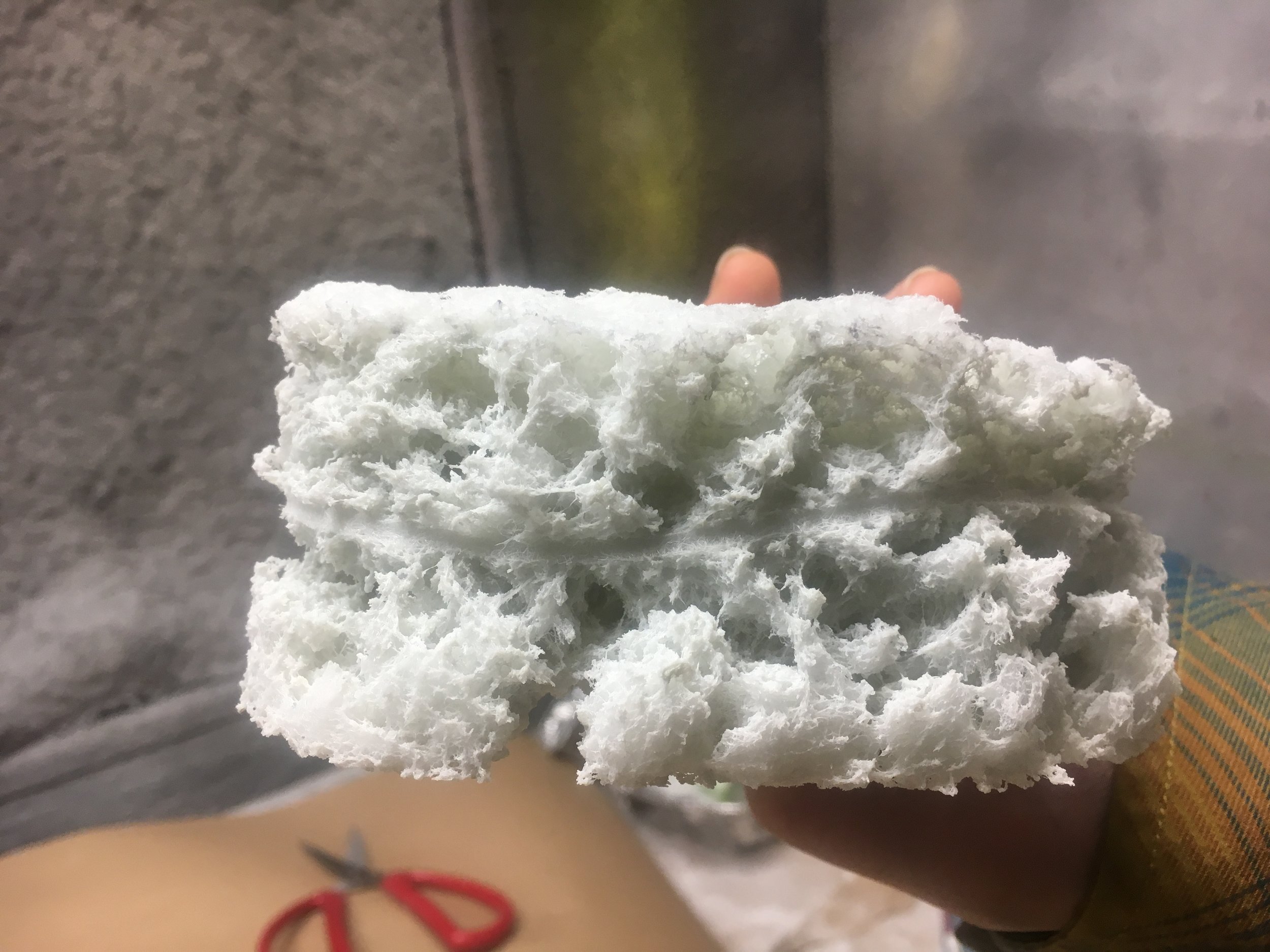
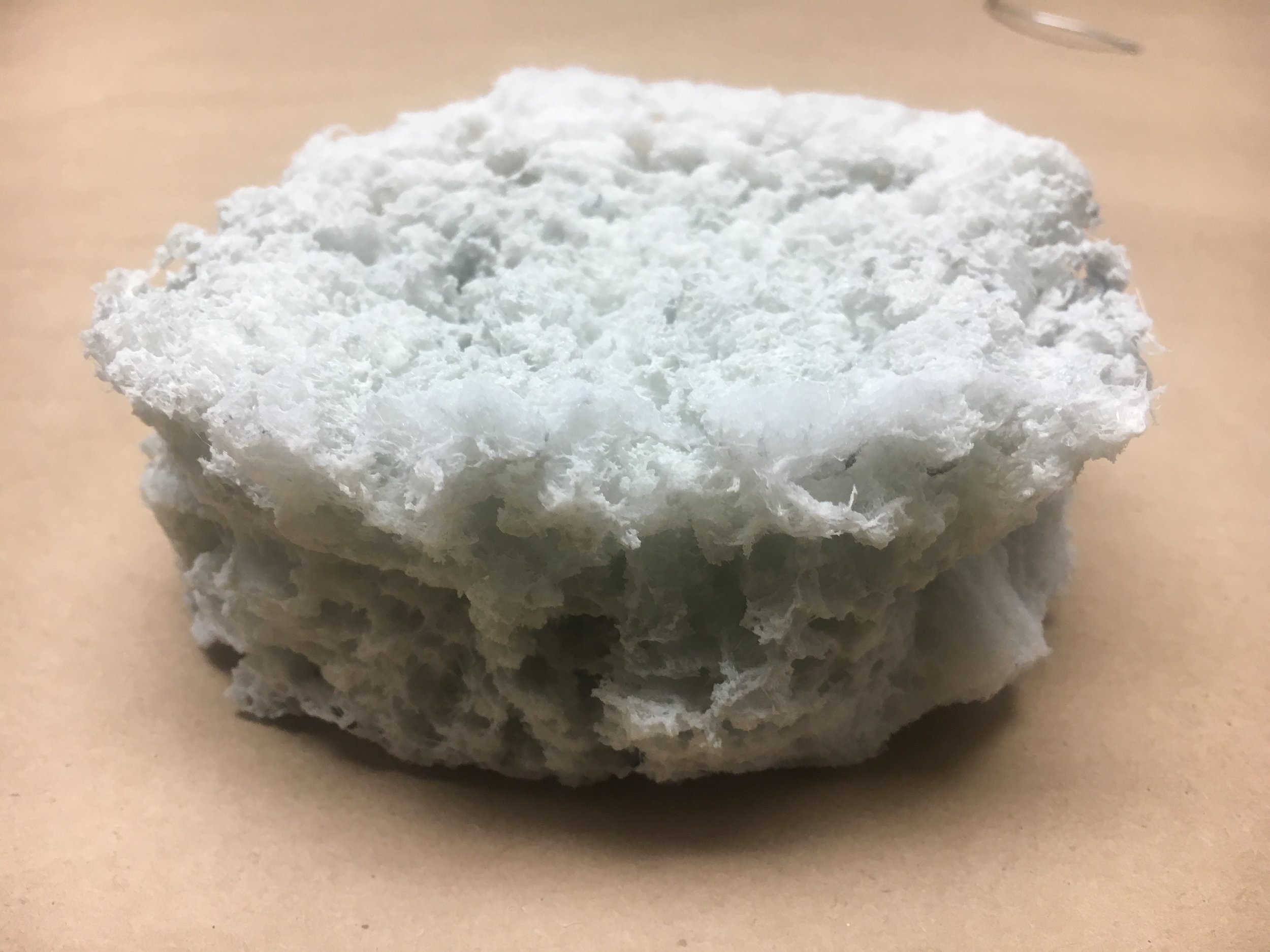
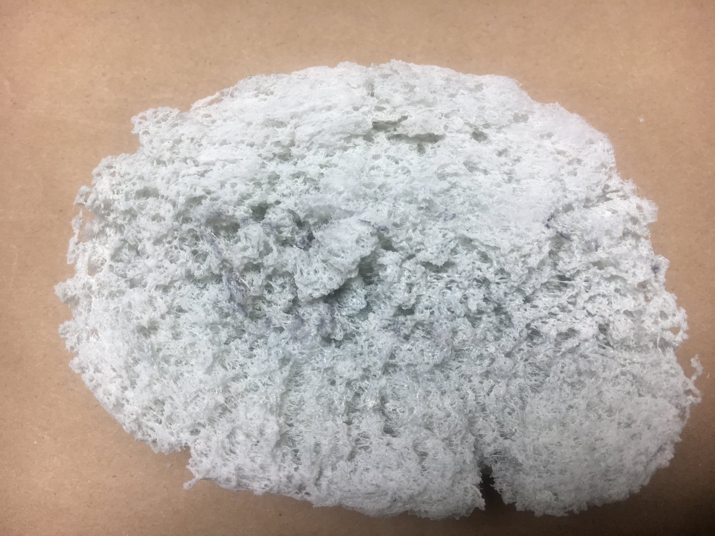
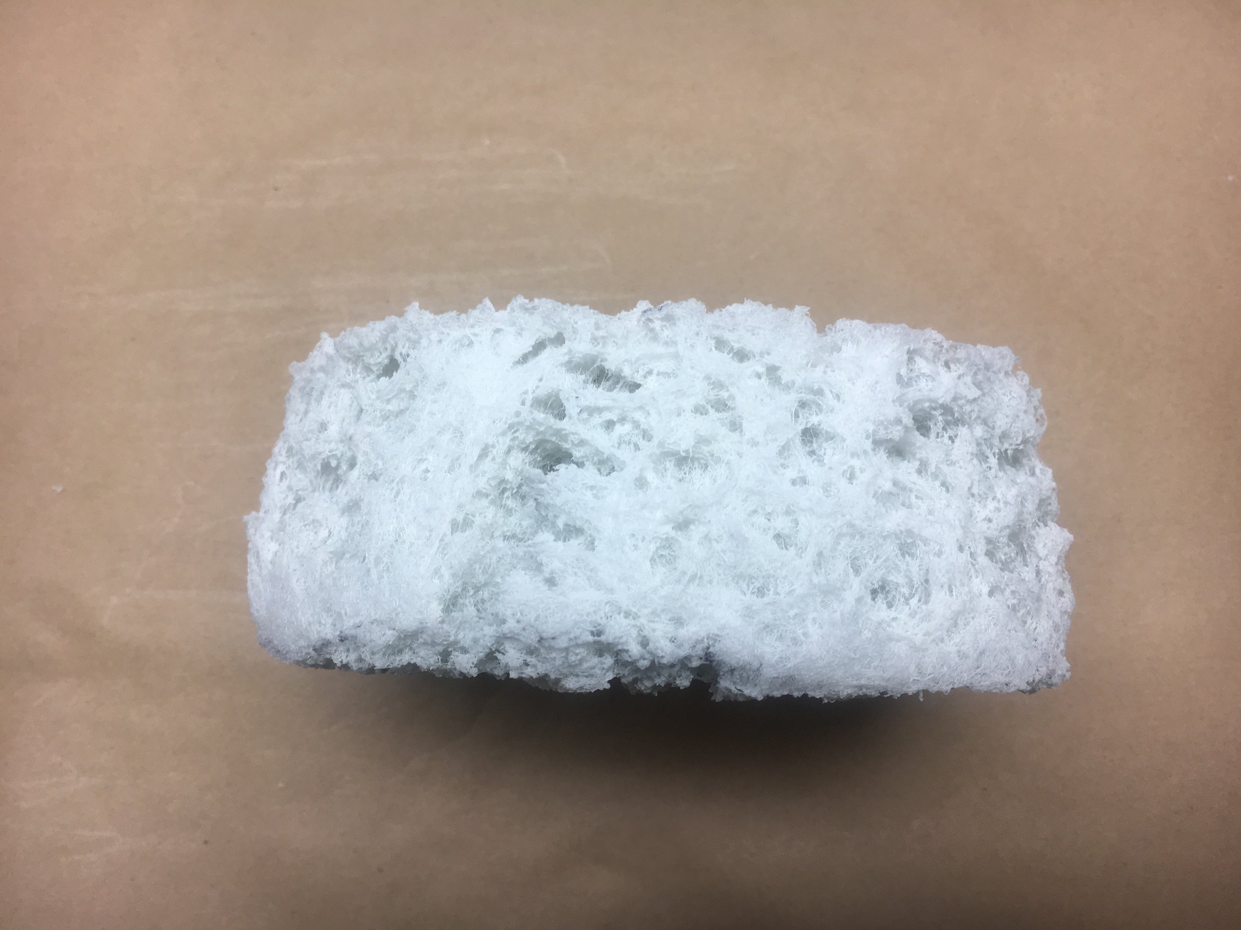
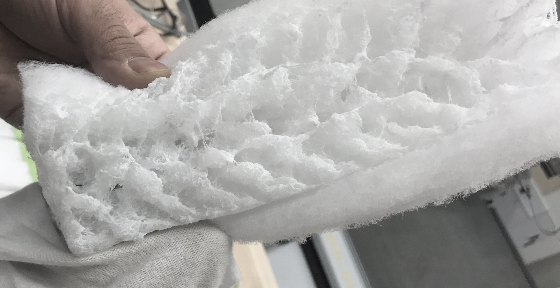
Material experiments were carried out to understand the phase-changing behavior of polyester fiber

1. Material
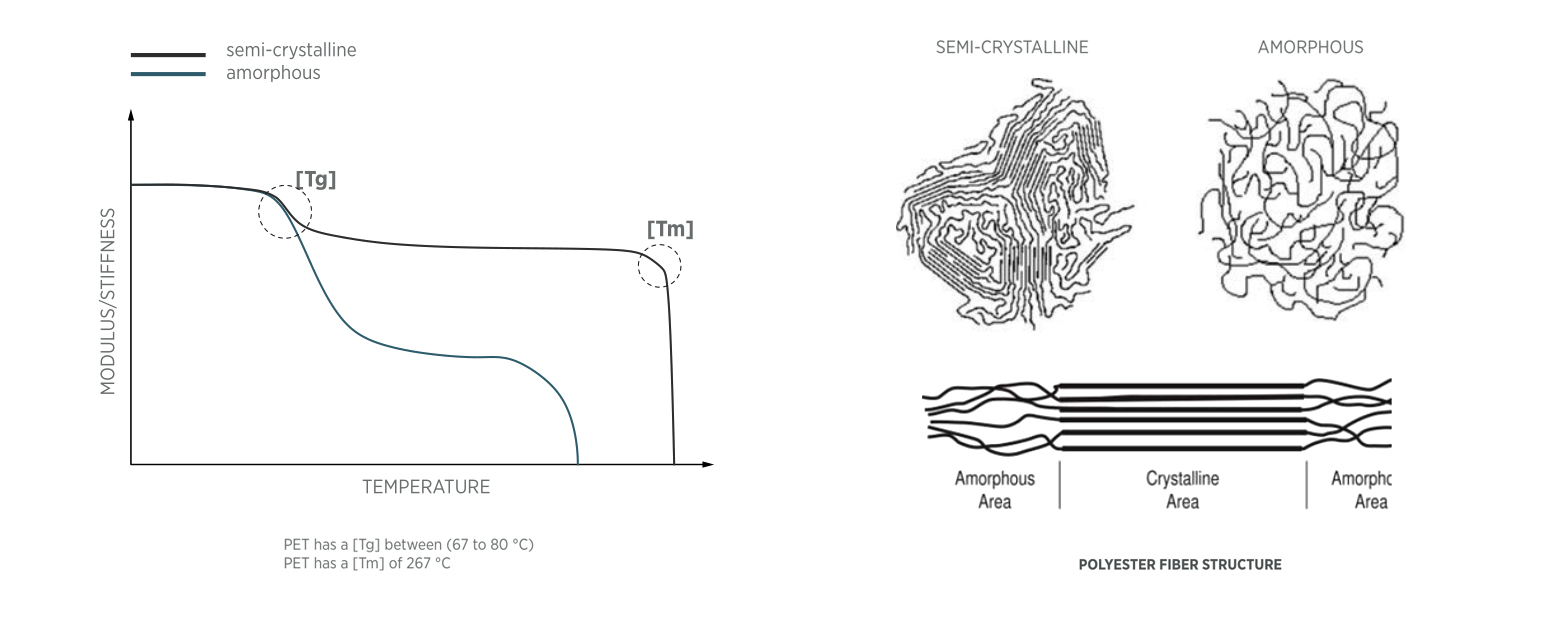
From literature we learned that polyester consists of 65-85% semi-crystalline regions, and 35-15% amorphous regions.
When heated, the amorphous region starts to soften gradually at about 200°C. while the crystalline region only melts abruptly at 267 °C.
Hence, there is an opportunity to exploit their different thermal transition behaviors.
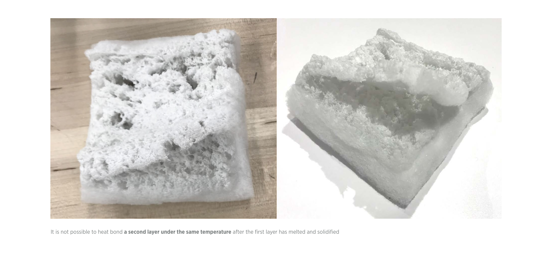
If we can maintain 200°C < T < 267 °C for some period, we’ll be able to melt the amorphous part to thermo-bond neighboring layers of material together to form desired shapes, without affecting the strength of semi-crystalline zone.
That means we have chances to vary the local stiffness of the polyester material.
Experiment<1>
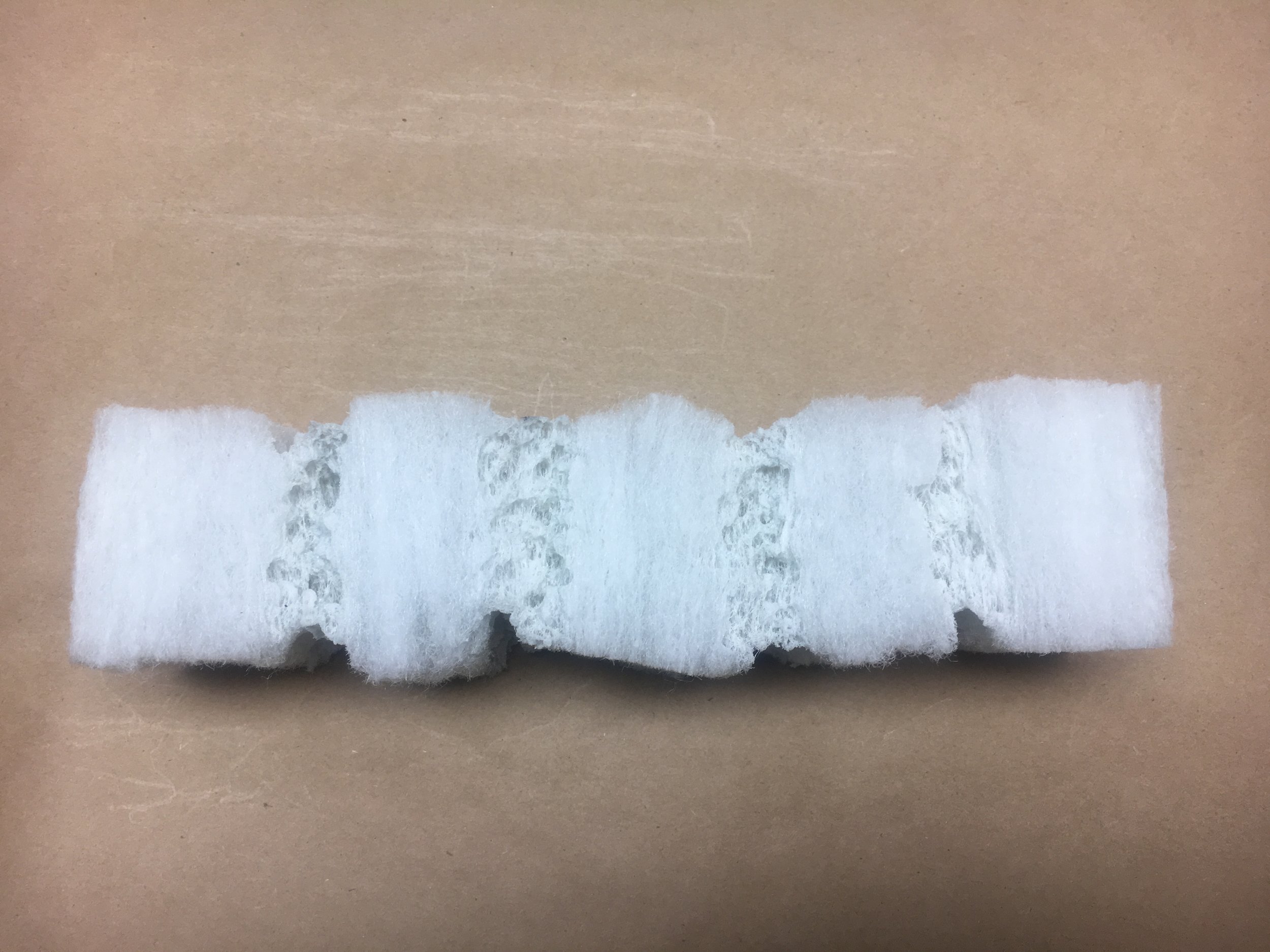
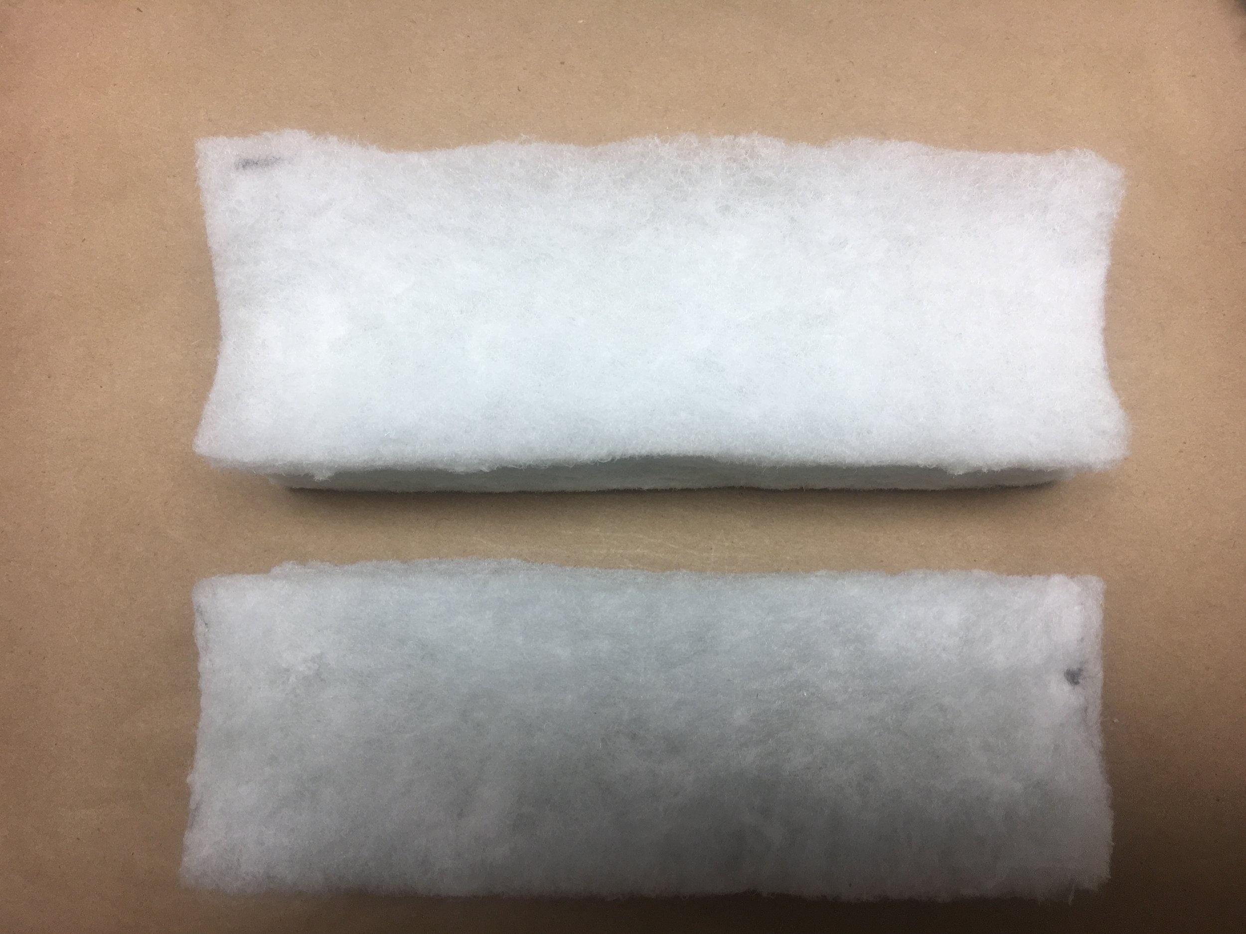
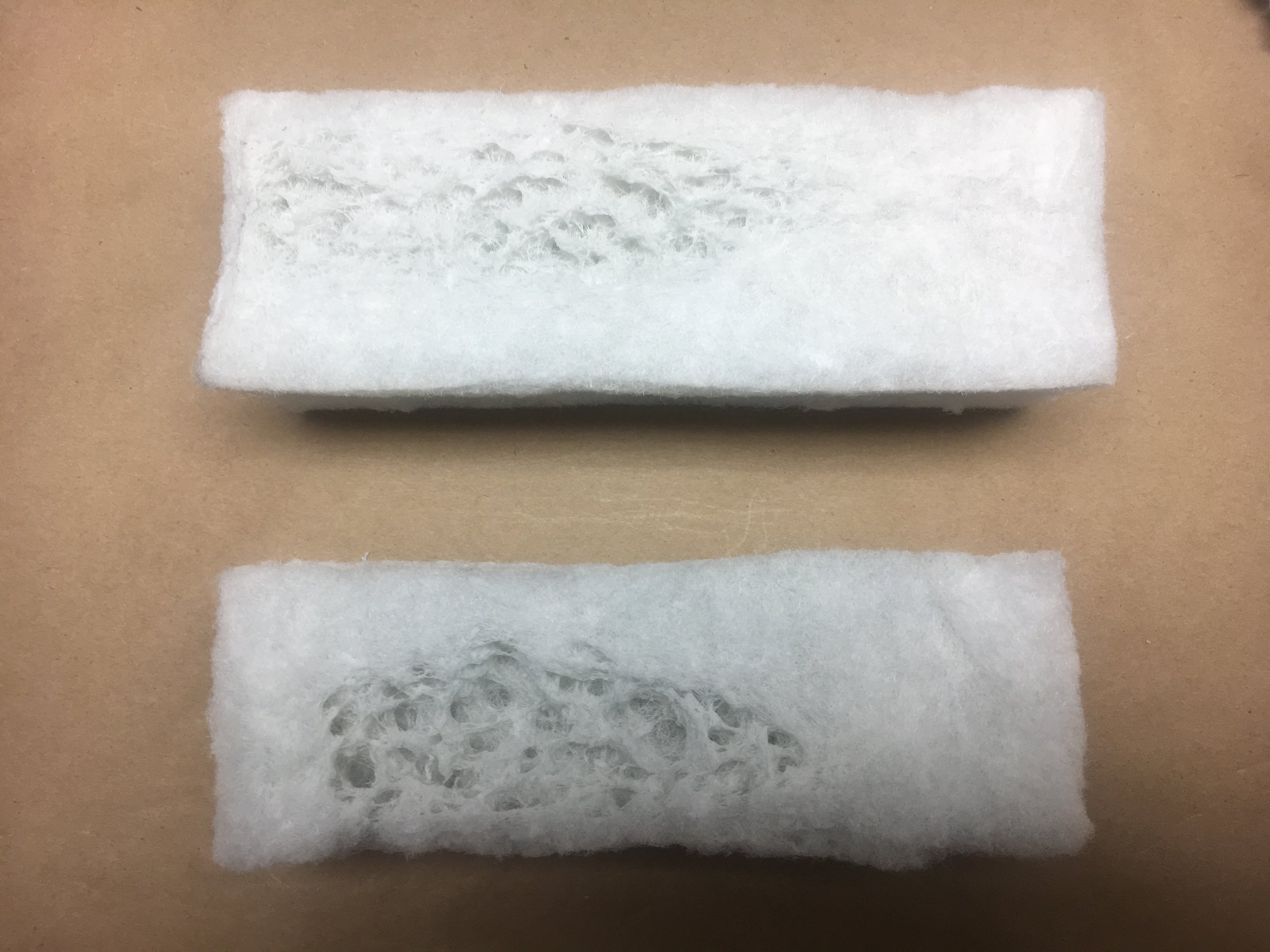
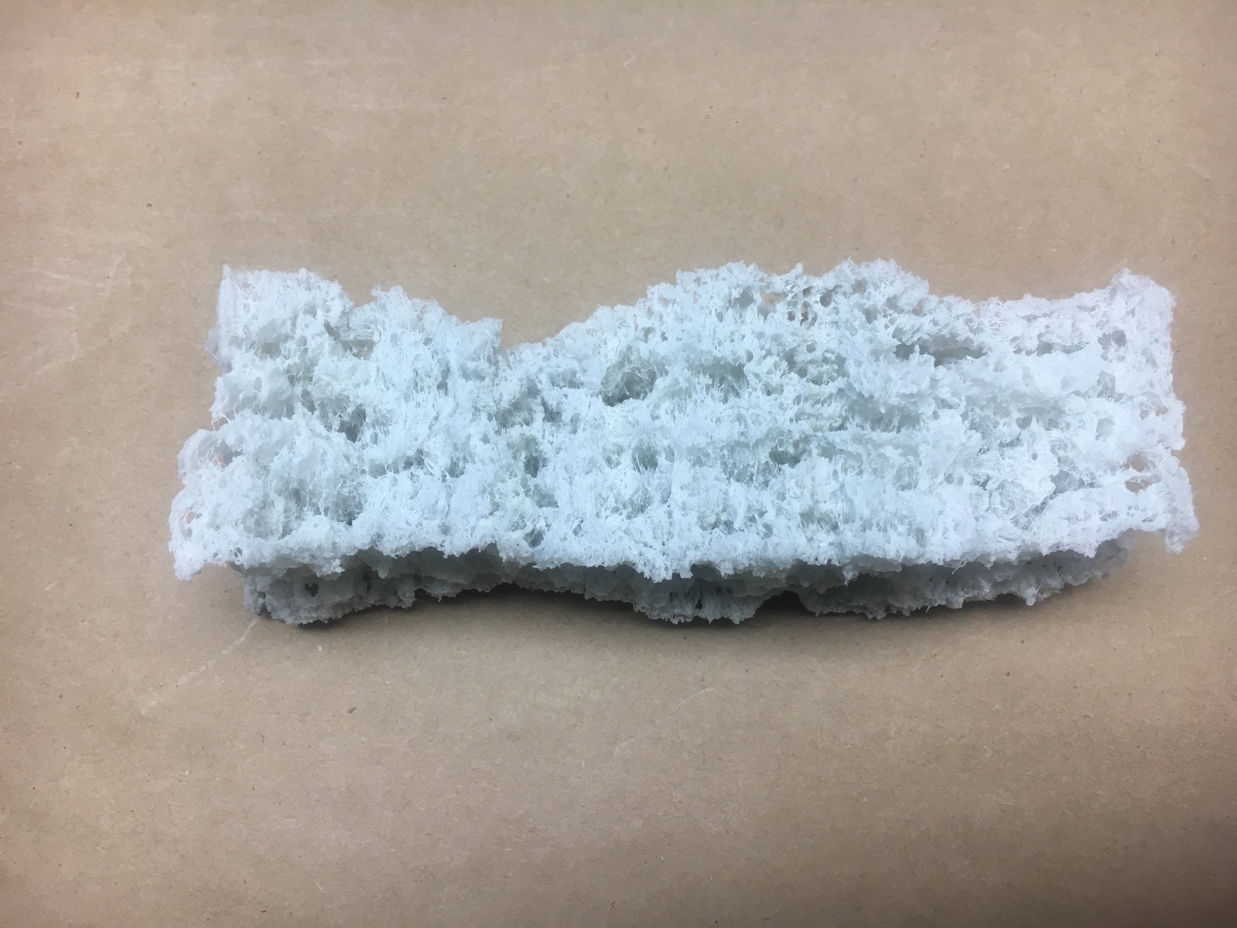
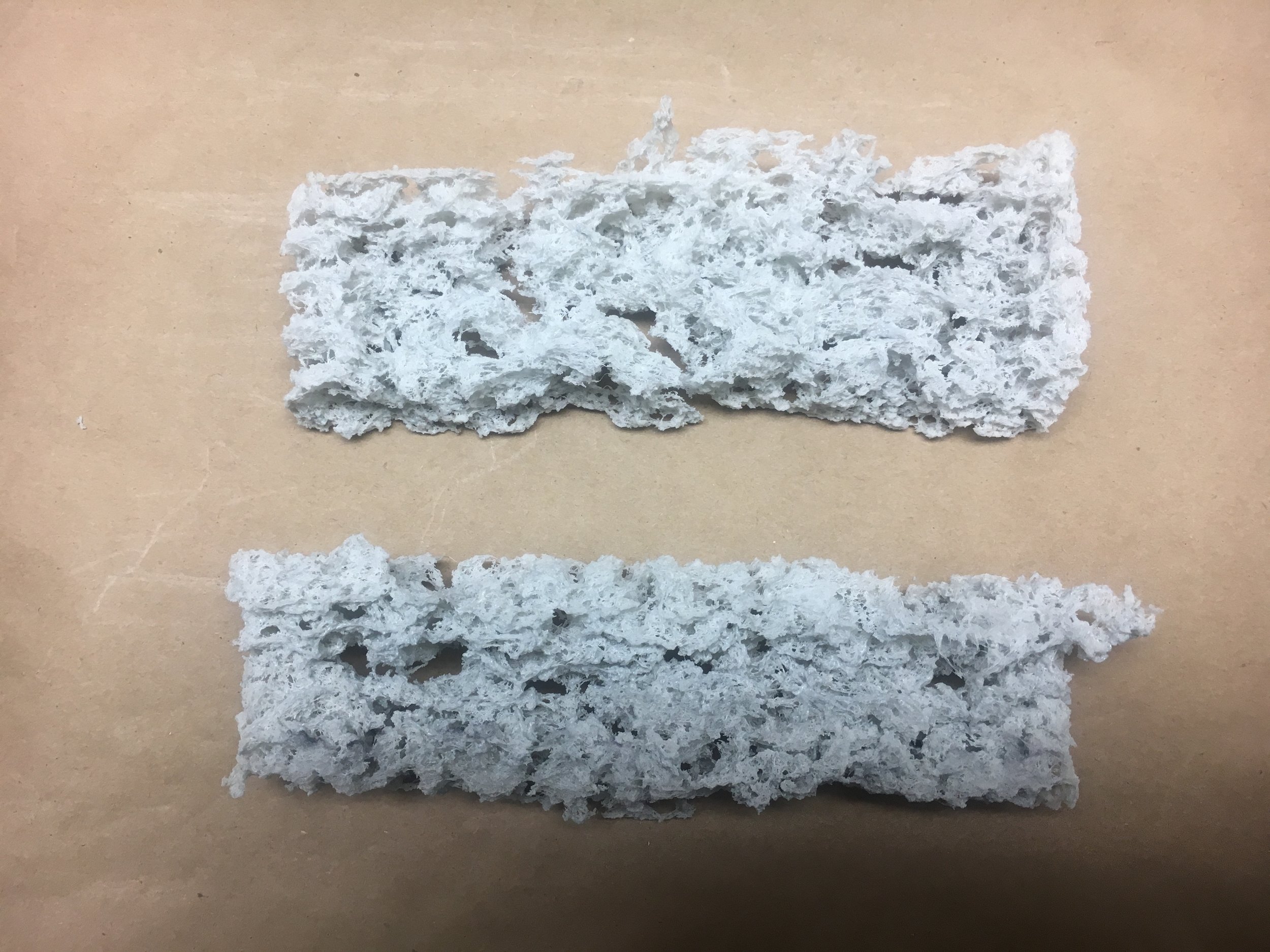
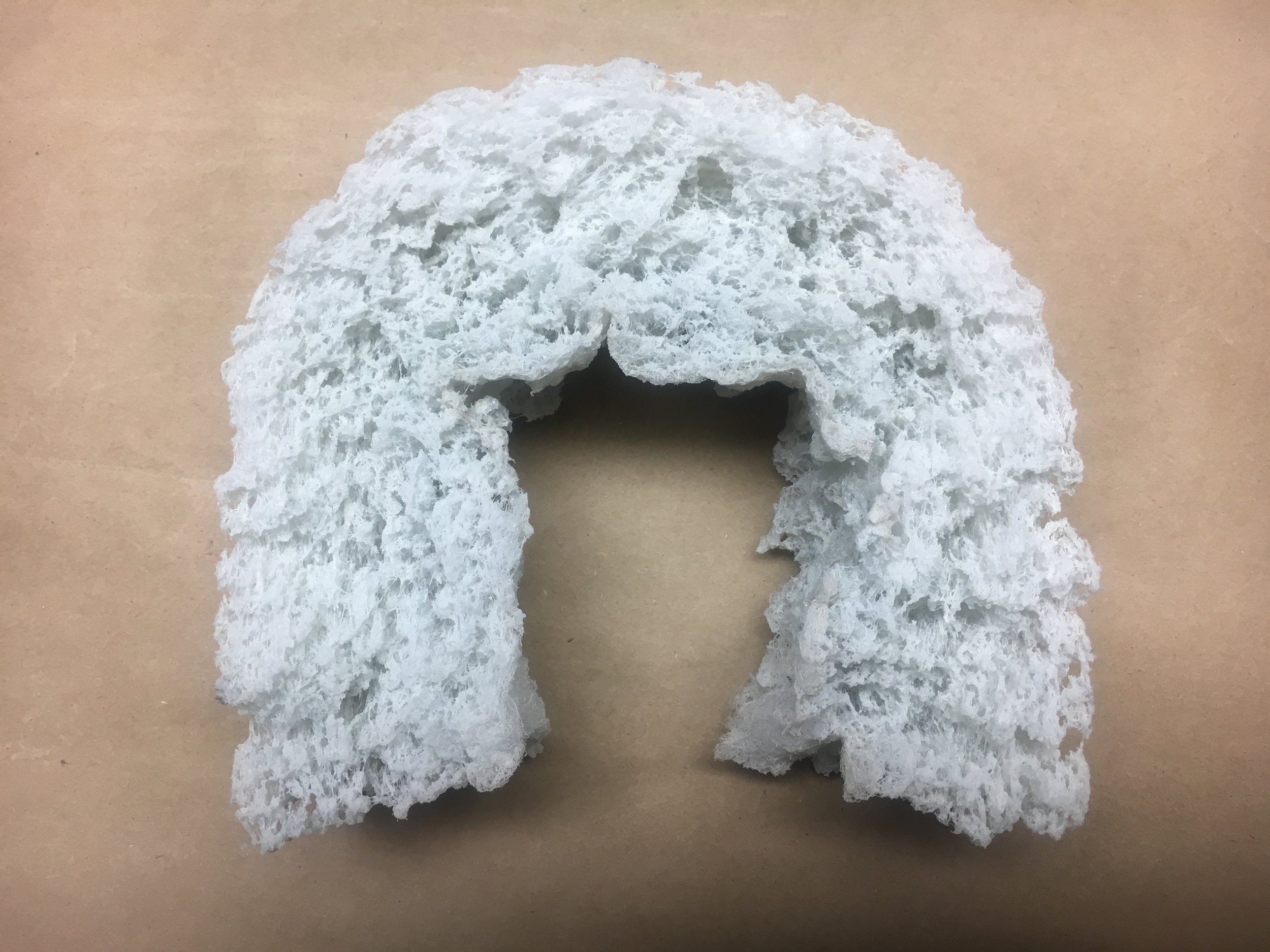
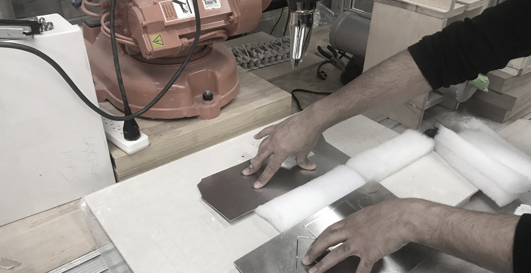
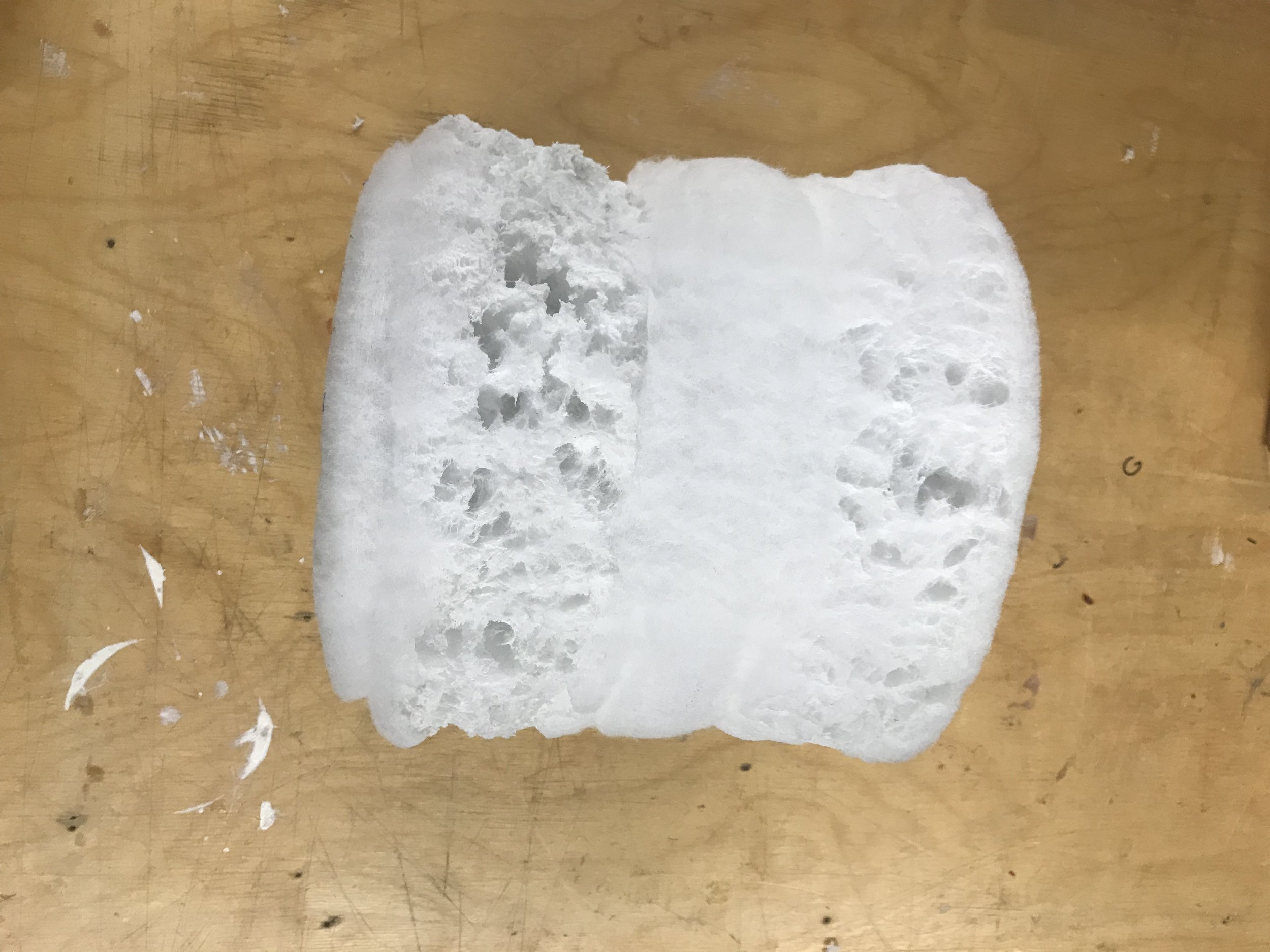
1.1 heat the polyester samples manually with a heat-gun
1.2 try varying local stiffness by heating selected regions 1.3 encase the material while heating for deformation.

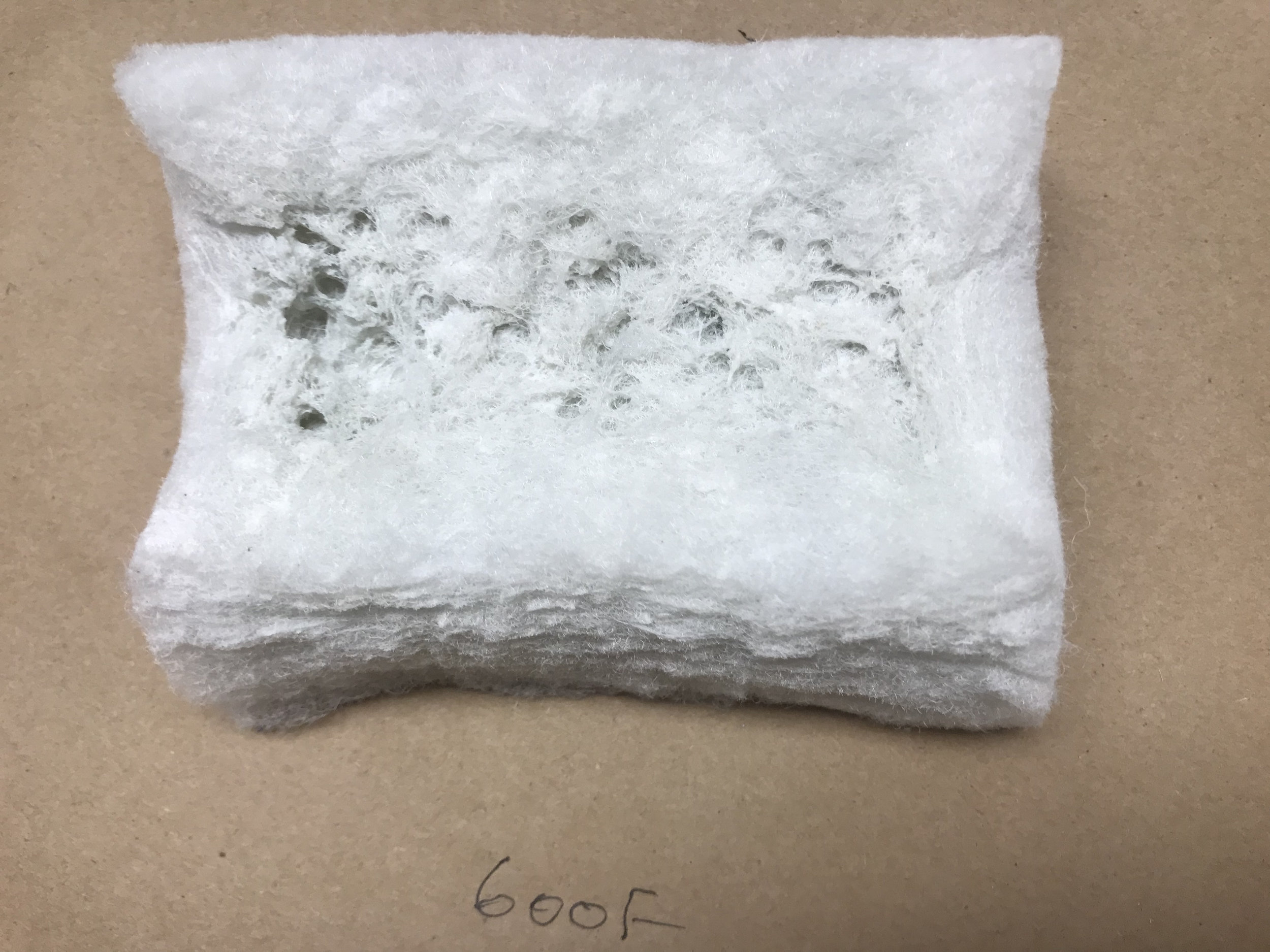
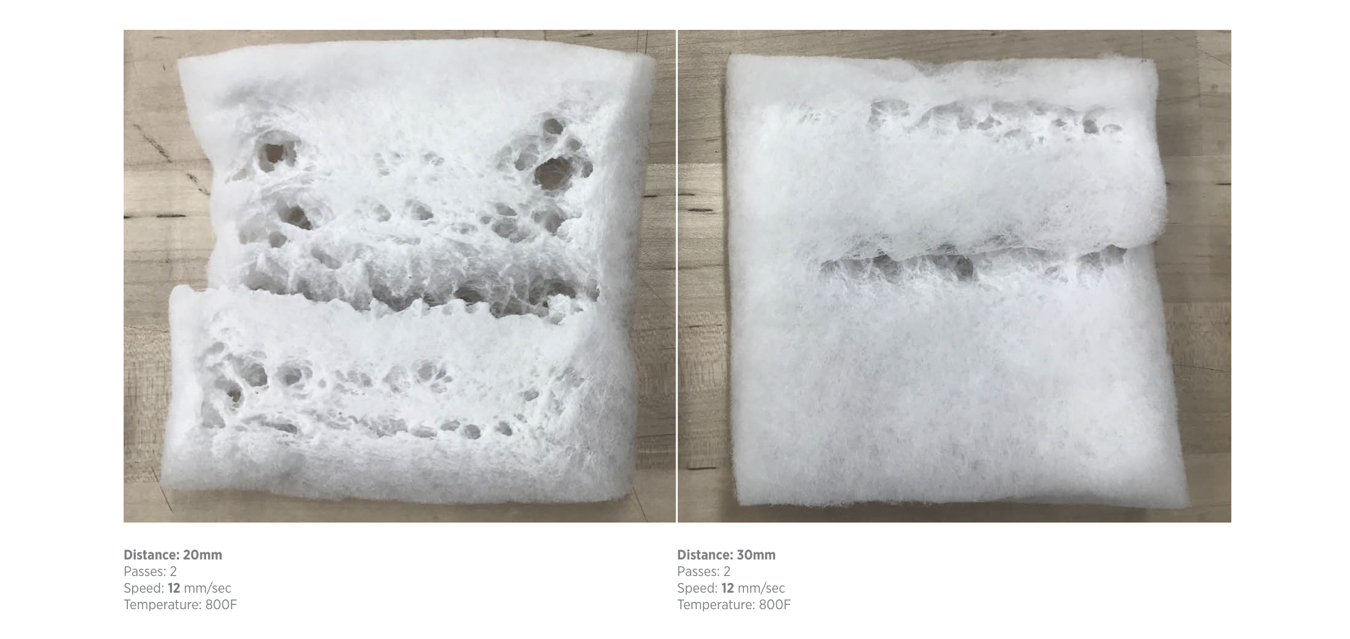
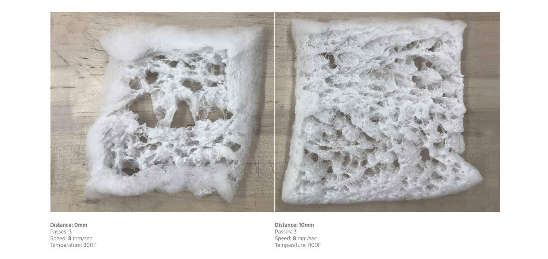
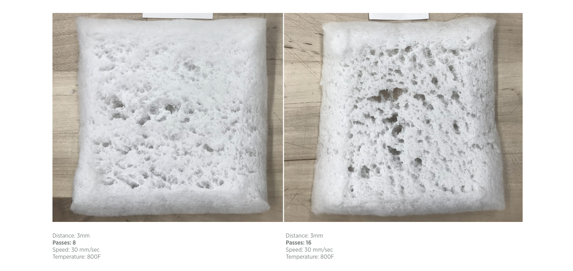
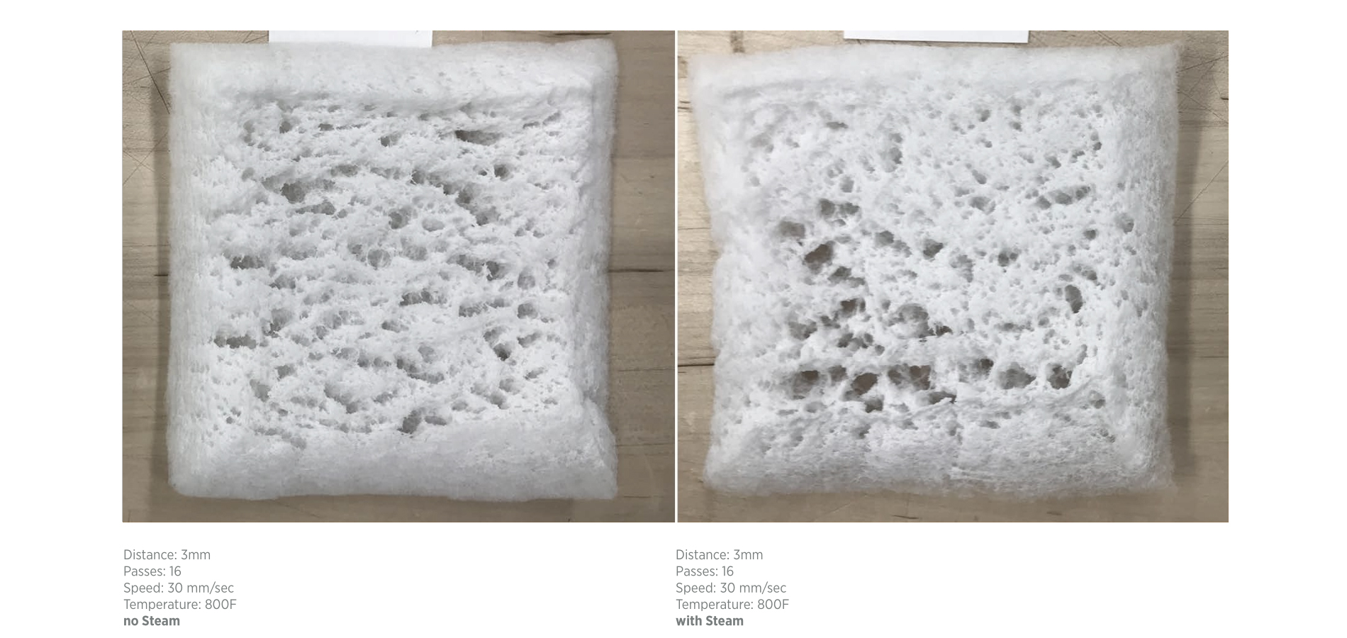
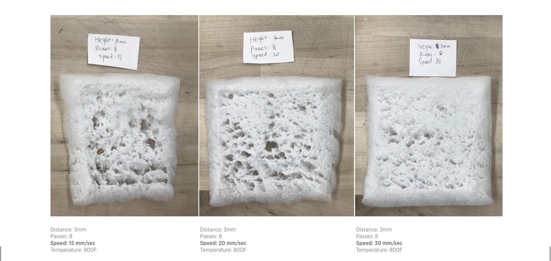
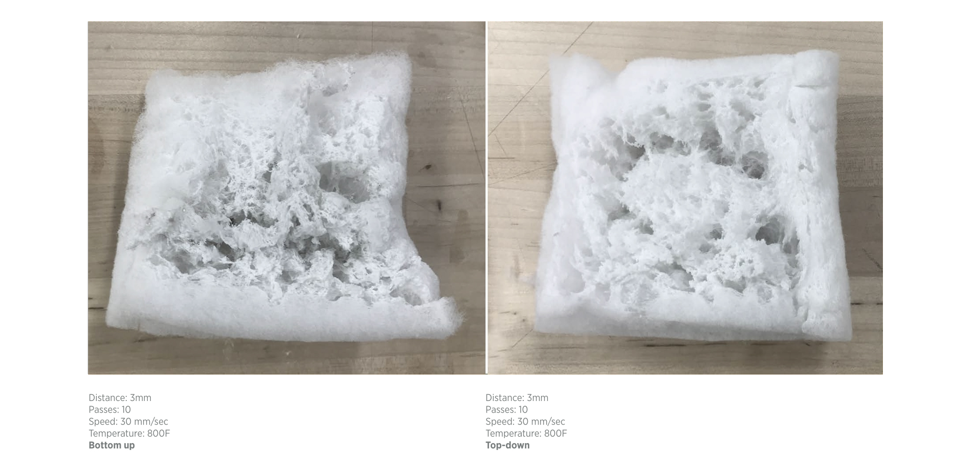
Experiment <2>
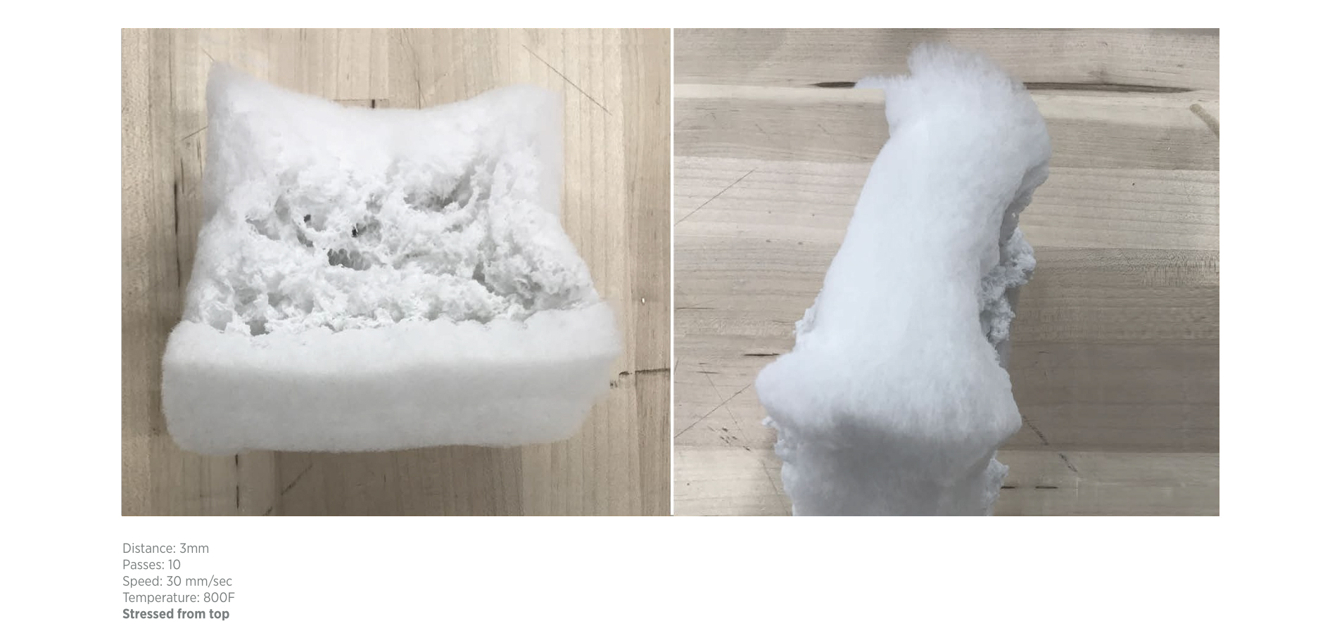
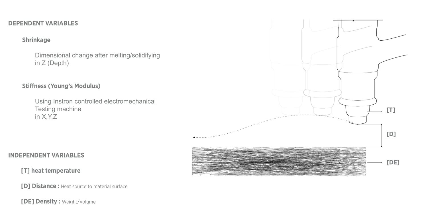
program the robotic arm to apply heat to polyester samples at different distance/ horizontal speed/temperature/number of passes/vertical direction, with or without steam/stress.


Experiment <3>
From above experiments, we hypothesized heating distance, temperature, stress(material density) are the most important factors
affecting the phase-changing behavior of polyester. Though the amount of steam seemed equally important, it is hard to control,
so we decided to focus on these 3 factors.
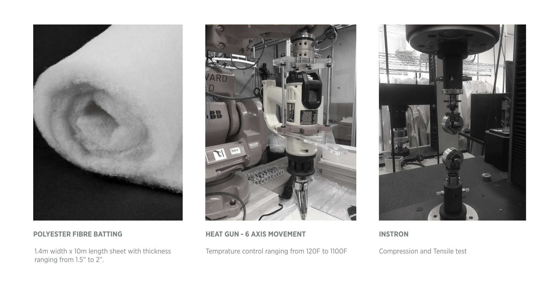
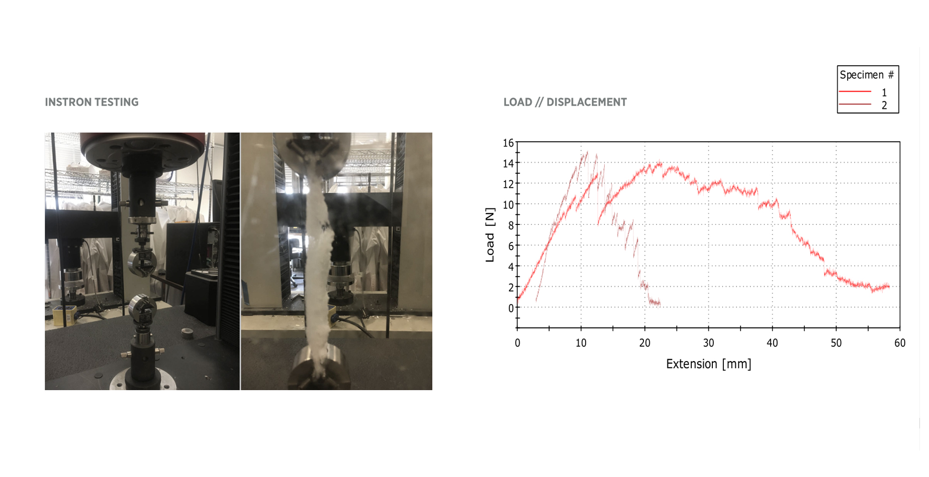
An Instron 5984 machine(thanks to MIT Mechanical Engineering Dept.) was used to measure the Young's Modulus, which indicates the tensile/compressive strength of the material.

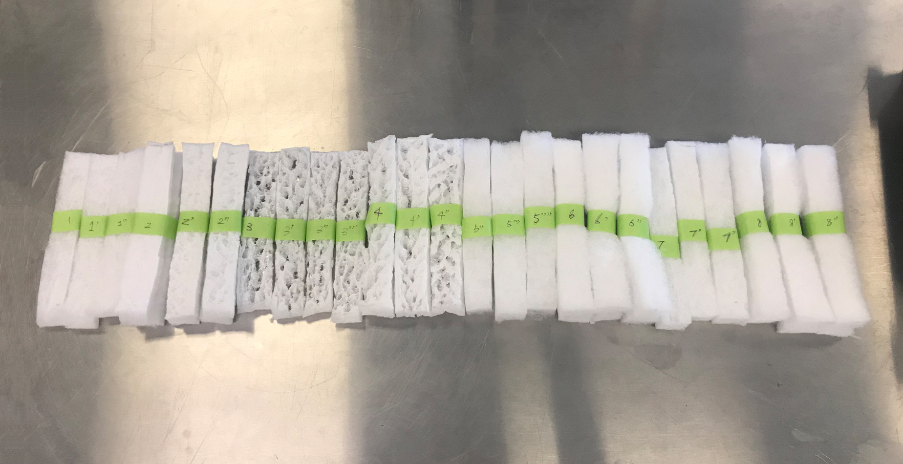
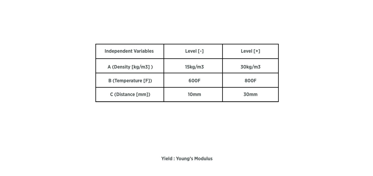
Design of Experiment
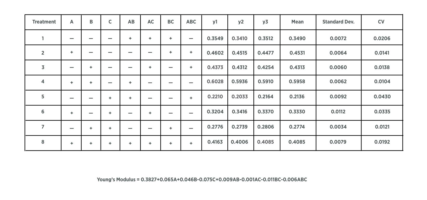
We leveraged a DOE mechanism to study the effects of these factors on the resulted stiffness of the thermo-bonded material.
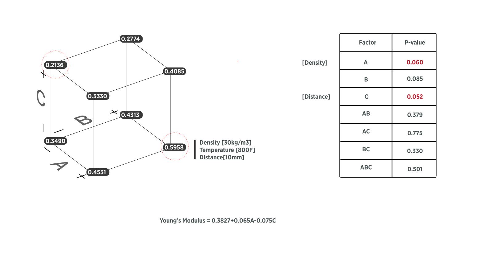
The DOE result analysis revealed how Distance(of the heat source to the material surface), Density(weight to volume ratio of the material),
the 2 key factors influence the tensile strength of the resulted material, which provided a basis for our smart fabrication techniques.
2. Computation
After the material study, we were pretty confident about how to generate stiffness gradiency in polyester.
Then the question became, what to generate, and why?
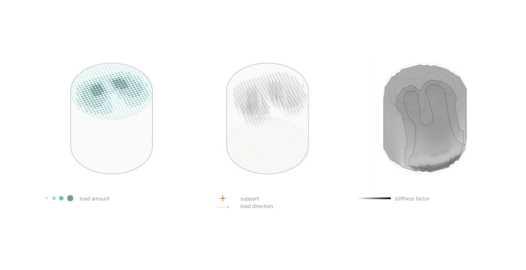
Gradient instead of homogeneous material property distribution enhances structural (load-bearing) efficiency, affords idiosyncratic interactions which meet certain emotional/cognitive/behavioral needs of the user.
As a start, we decided to focus on structural efficiency.

Then the question became, what kind of gradient stiffness distribution in a chair would be most efficient for load-bearing?
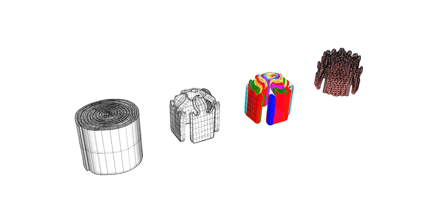
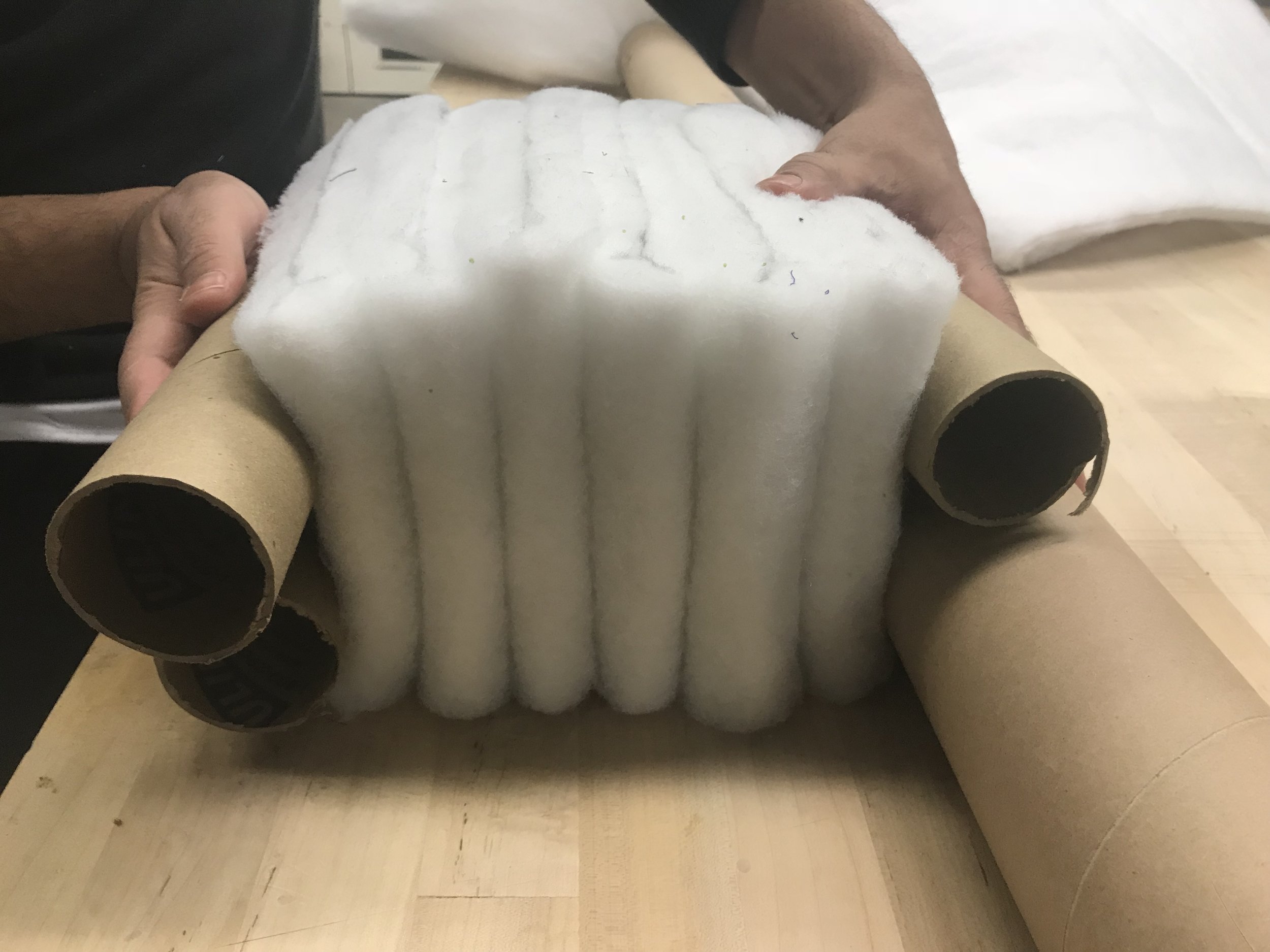
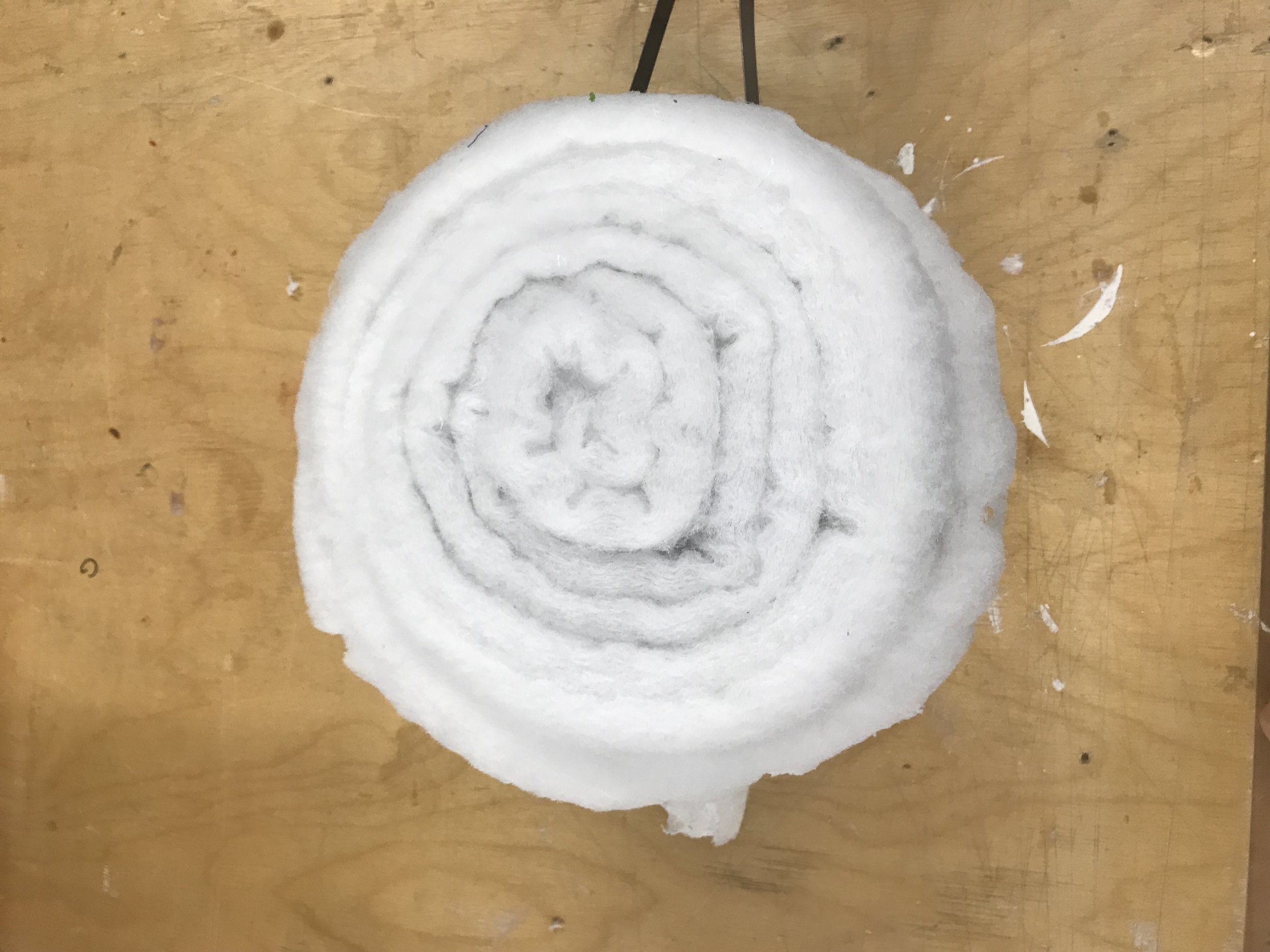
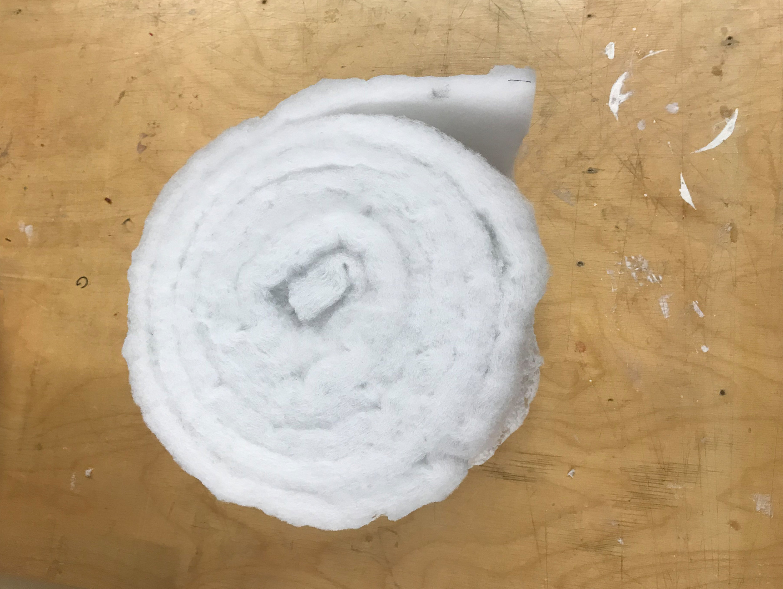
To answer the question, first a rolled cylinder representing the chair geometry was modeled in Rhino.
In fact, the cylinder was rolled from one continuous sheet, for we intended to fabricate the chair from a polyester sheet rather than a chunk.
Topology optimization was carried out through Millipede for Grasshopper to maximize the overall stiffness while minimizing weight.
Result showed that maximum material stiffness (thickness) was required at the bottom periphery and the center (figure below).
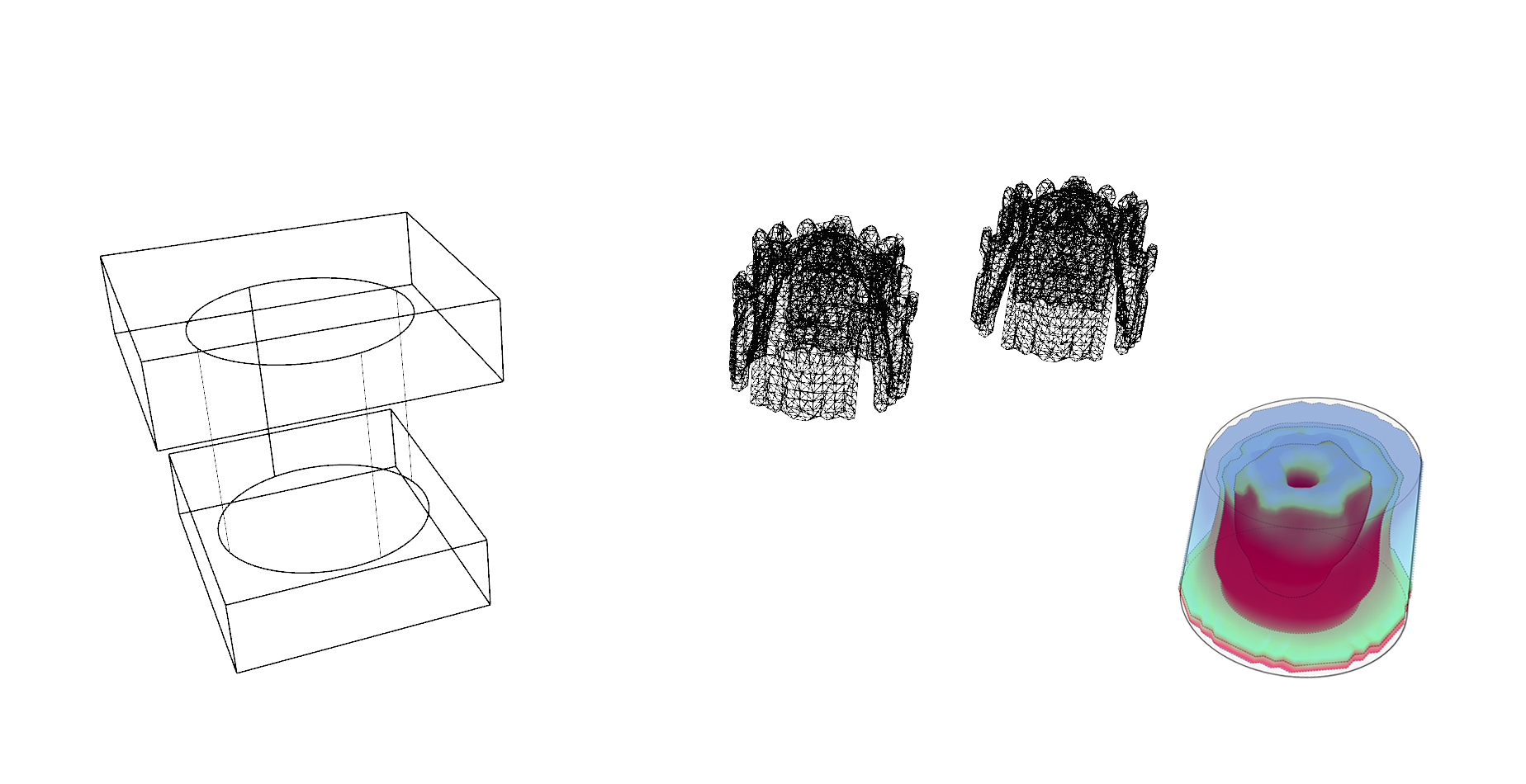
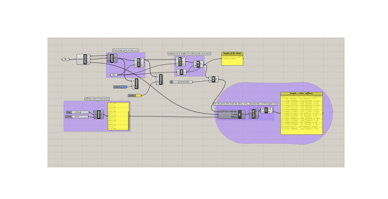
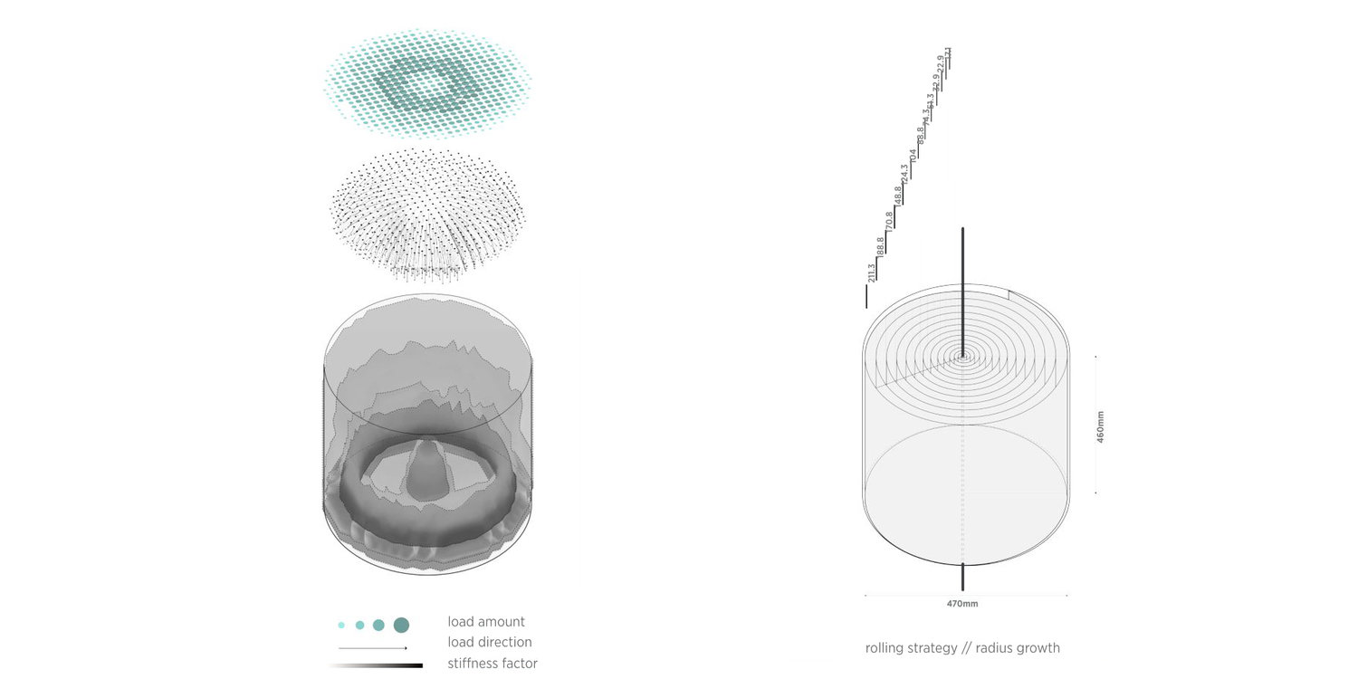
Topology optimization suggested the ideal 3D Stiffness Distribution in the chair model ranging from 0 to 1, and that was mapped onto a 2D Distance Value Distribution (between 10 and 30 mm) on a flat sheet. Because we had established the relationship between the desired material stiffness and the heating distance through the previous experiments.

Thus, we finally arrived at the 2D Distance Value Distribution Map, which would guide the following robotic fabrication process.

3. Fabrication
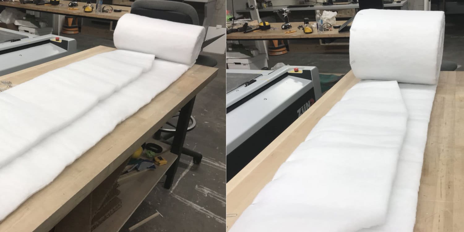
The fabrication process involves [cutting+folding] & [rolling+robotic heating].
Together we were able to fabricate a cylindrical chair with the desired stiffness distribution.
Note that in the following video, rolling was done manually, which would be replaced by a rolling machine in its future version.
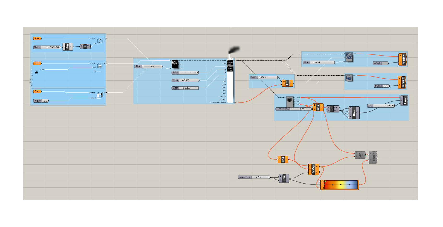
Digital Workflow: From Computation To Fabrication
[cutting+folding] strategy affords the density differentiation while [rolling+robotic heating] ensured the distance variation during heating.
The data (density & distance values) was fed through interface programs (machina for grasshopper, CNC software) into the fabrication system.

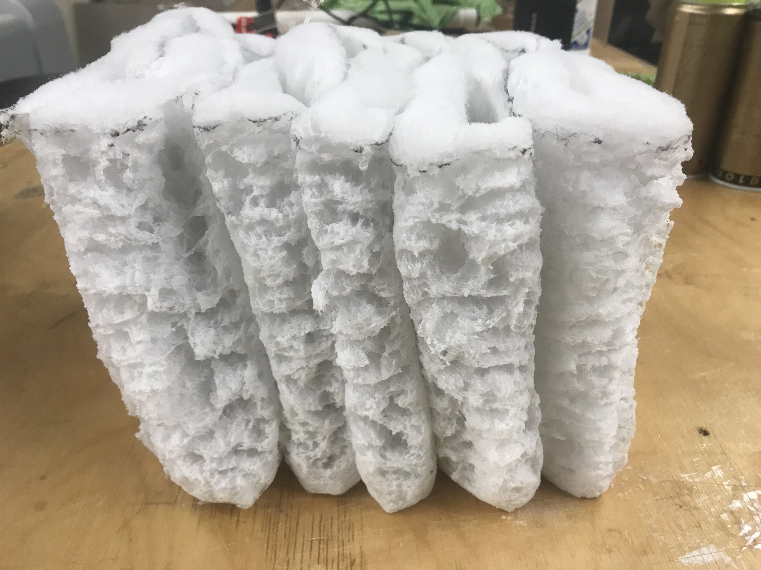
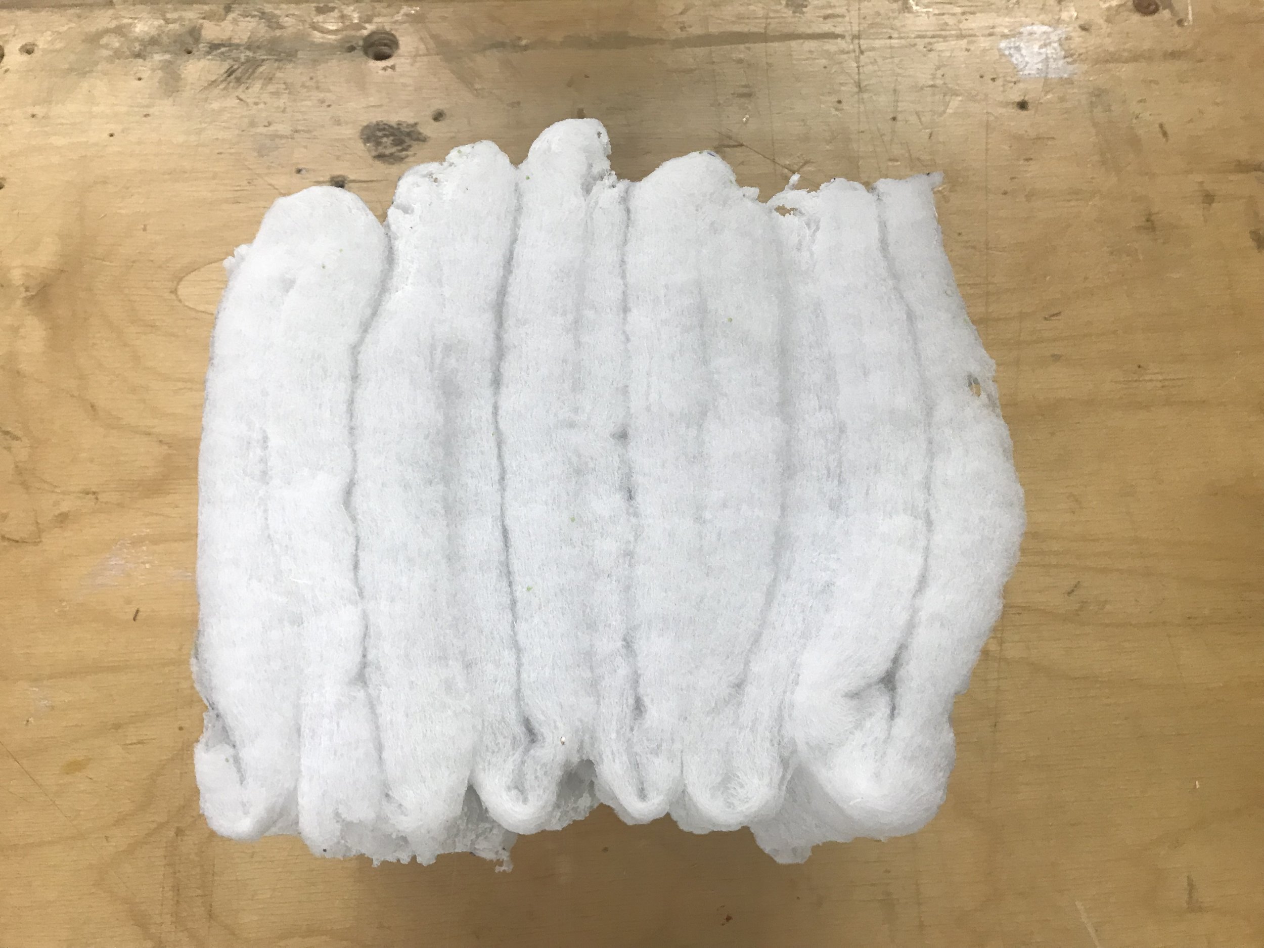
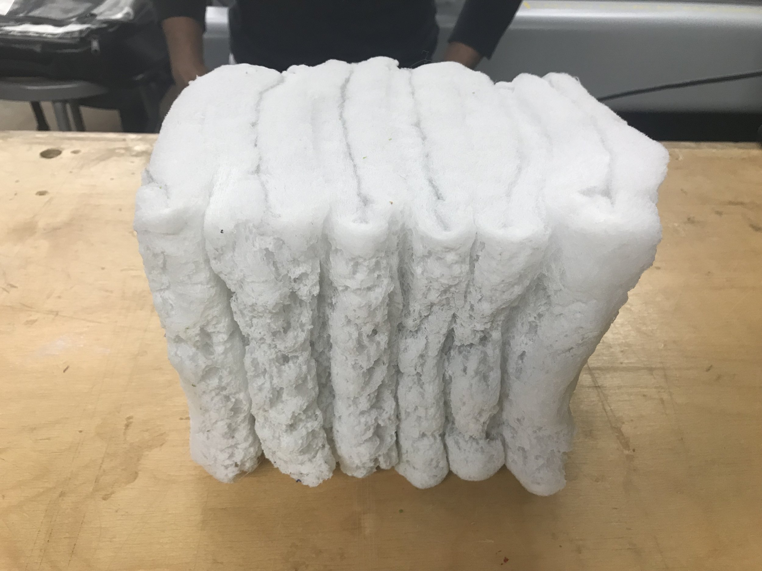
1. [Cutting + Folding] -> Density Differentiation
We invented a clever cutting+folding strategy so that the double-layered locations correspond with the higher-density points.
Besides, the central-symmetrical cutting method led to two identical pieces of cuts, resulting in zero material waste.
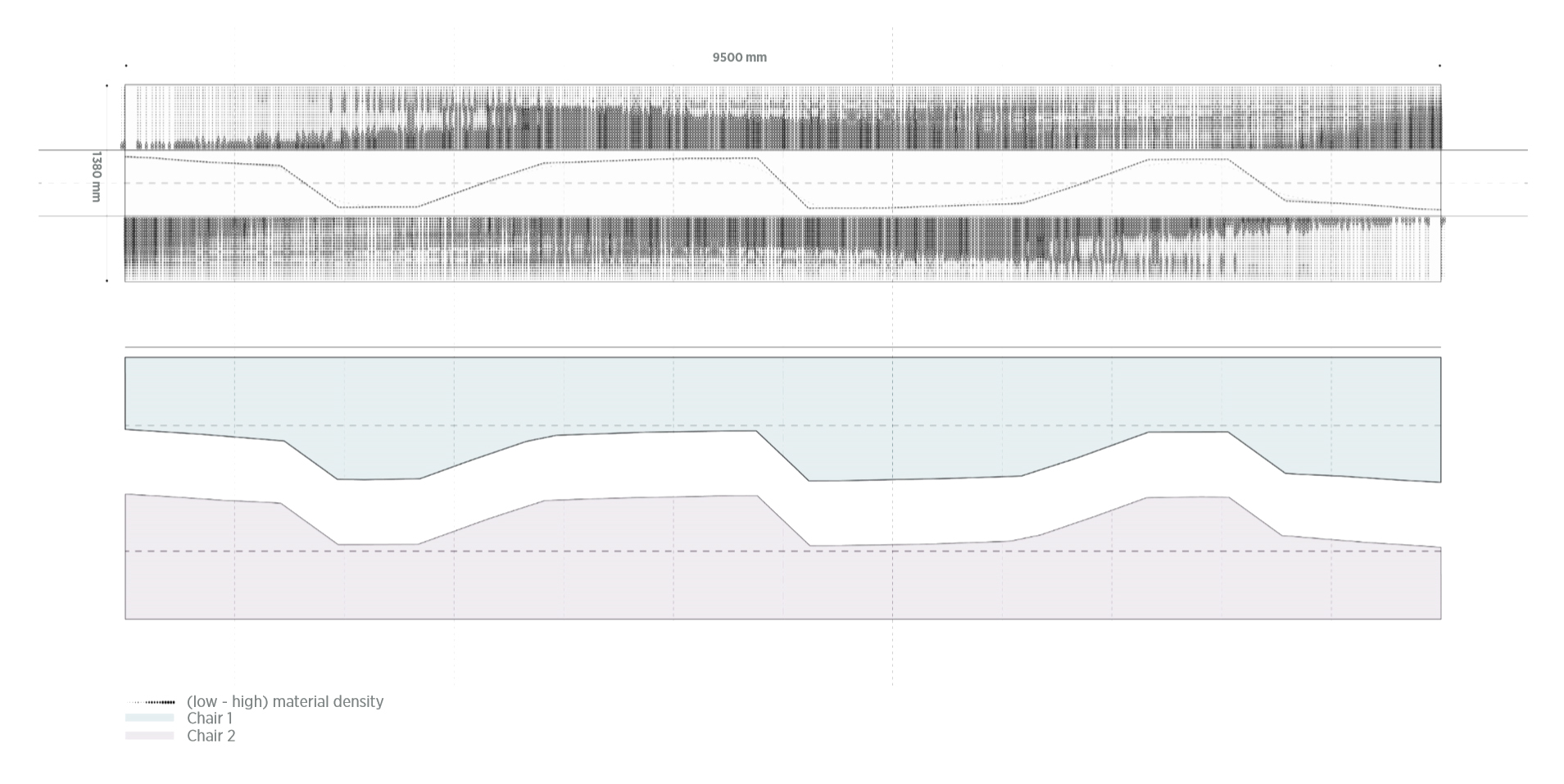
Actually the idea came from paper prototyping.

Later it was automated in Grasshopper for an optimized cutting path with both thee ideal density distribution and the least waste.
2. [Rolling + Robotic Heating] -> Distance Variation
A 2D distance distribution map derived from the computational topology optimization result was used to guide the robotic heating process.
The robotic tool path was generated through Machina for Grasshopper3D.
A 6axis ABB robot with a customized end effector to hold the heat gun was utilized for heating .
In the next version, rolling would be automated by an electric motor and an Arduino board paired with our customized pressing table.

4. Exploration
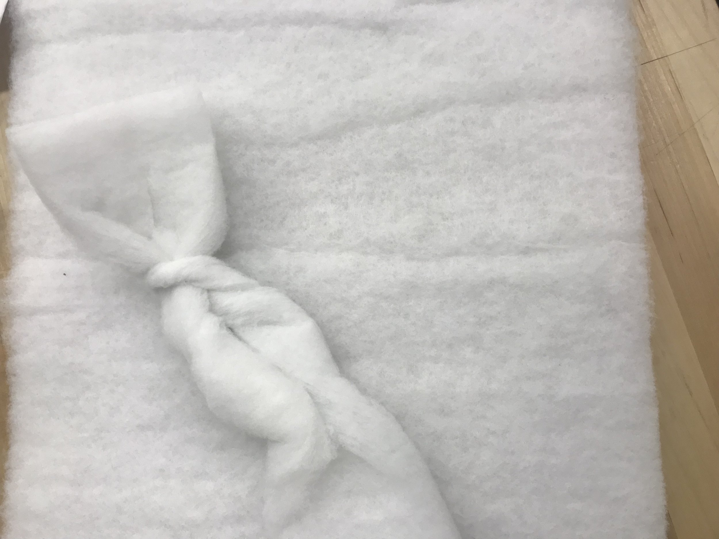
(1) Zigzag Folding
Zigzag folding is one way to bond material layers together. But it also limits the resulted geometry. Besides, it tend to induce a shear effect when load is applied in some direction, impacting the structural performance.
(2) Local Cutting & Folding
Local cutting/folding technique was inspired by Chinese paper-cutting tradition. It allows for more intricate geometries and density differentiation. However, it is hard to precisely control.
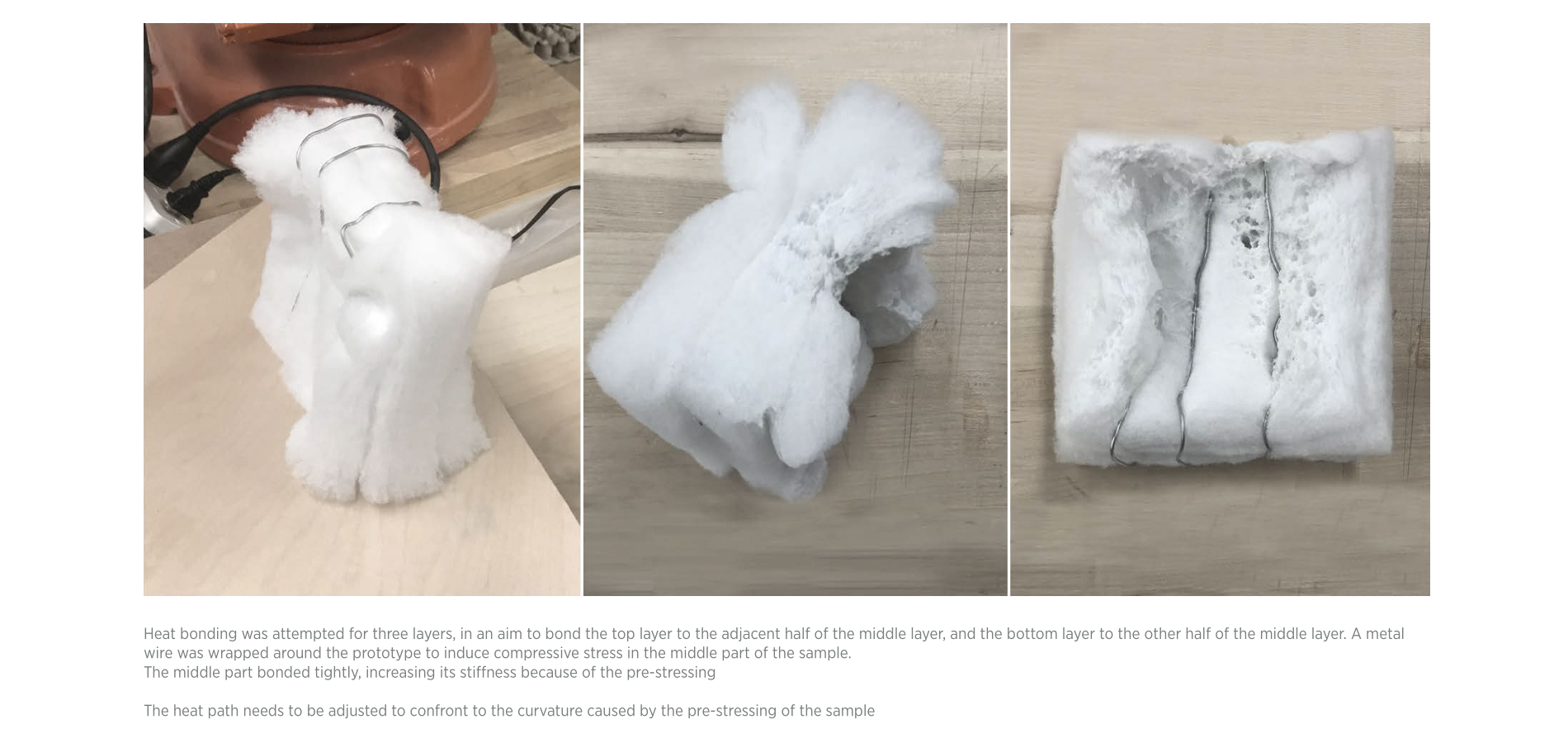
(3) Stressing
We tried using metal string/stripes to stress the piece while applying heat to it.
The result is interesting. Stress influences material density, which affects the resulted stiffness. We plan to further investigate the effects of stressing for the generation of more complex geometries.
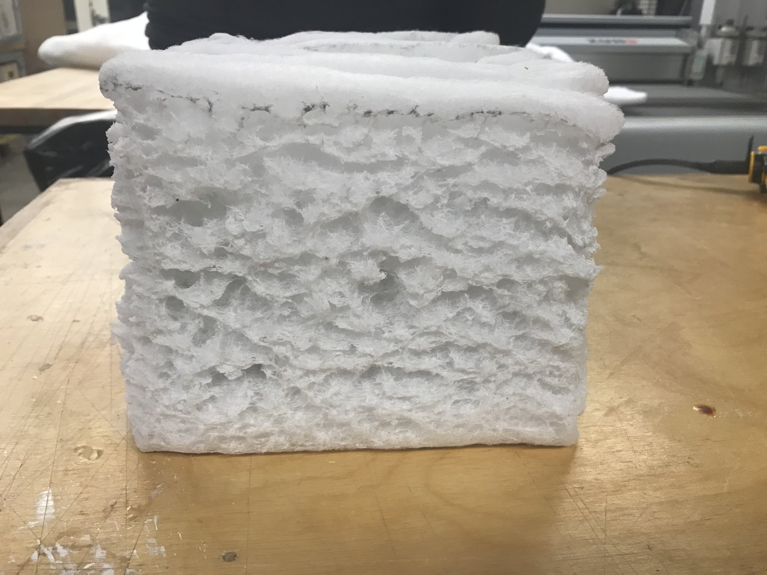
Final Product


Evaluation
How can we prove that our chair has achieved the desired distribution of stiffness, as calculated by the algorithm?
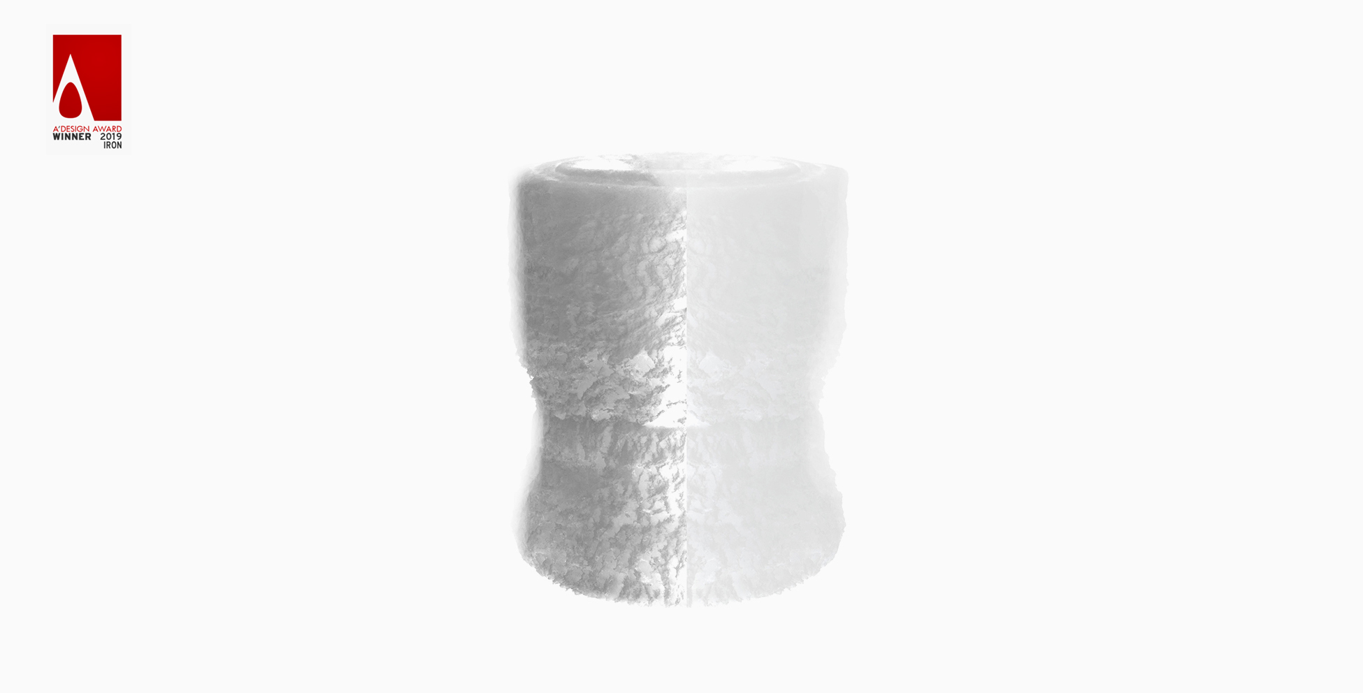
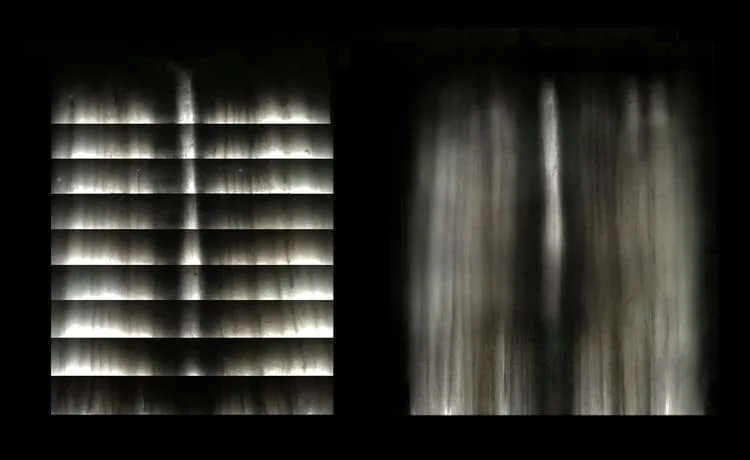
To evaluate the stiffness distribution in the prototype, we used a technique similar to tomography.
We photographed the chair in a dark room, where the only light-source was a horizontal light bar that “scanned” the chair from top to bottom.
Hence, in the places where the material is “denser”(higher stiffness), less light would go through.
Hence the denser the area, the darker the image.
To our delight, “tomography” result suggests the actual stiffness variation in the prototype was identical to the computational model.
Take-Away
“ 1. Start from observing material phenomena.
Design the artifact as if no other material can afford the design.
2. Design Exploration should never be arbitrary.
Instead, it should be structured, deliberate, and quantifiable.”

70% vs 30%
What is marvellous about this project, is the echo of “70% crystallinity vs
30% amorphousness” at both the micro and macro scale.
Crystallinity reminds me of the digit, the bit, the unambiguous,
while amorphousness speaks to the ever-existing chaotic nature of
everything physical.
The digital workflow ensures
a reliable copy of heat:chair every time it’s being manufactured,
However, there will always be tiny dislocations,
erratic little disobedient fibers that go beyond their programmed “boundary”. Isn’t it beautiful?
Future Work
Form: design and fabricate other geometries, perhaps with the other fabrication strategies previously explored
Material Behavior: design objects that can exert certain behaviors afforded by their varied stiffness
3 Dynamic Stiffness: investigate means to manipulate material stiffness in real-time, for potential HCI applications
4. Effects of Steaming: use the Design of Experiment approach to evaluate the effect of steaming on local material stiffness
5. Scale: transition the process to a robotic environment using the ABB robot 440-L30 for large-scale prototypes
Download: Heat Chair Design Report
Controlled Stiffness Gradients through Thermal Bonding and Density Differentiation - Heat Chair Paper